Introduction
Power quality is an important consideration in modern electrical power systems. Industrial facilities, commercial buildings, data centers and renewable energy installations increasingly use electronic equipment that can introduce harmonic distortion into electrical networks. These harmonics can increase power losses, cause overheating, interfere with sensitive equipment, and reduce the overall efficiency of electrical systems.
A harmonic mitigation device is an electrical device or system designed to reduce harmonic distortion and improve power quality. Depending on the application, it may use passive filters, active power filters, hybrid filtering techniques, or specialized power electronic converters to minimize unwanted harmonic currents and voltages.
Harmonic mitigation is particularly important in installations containing variable-frequency drives (VFDs), uninterruptible power supplies (UPS), rectifiers, electric vehicle chargers, and other nonlinear loads. Selecting the appropriate solution can help improve equipment reliability, reduce electrical losses, and support compliance with applicable power quality standards.
In this article, we explore what harmonic mitigation devices are, how they work, their major types, advantages, limitations, and practical applications.
What Is a Harmonic Mitigation Device?
A harmonic mitigation device is equipment installed in an electrical system to reduce unwanted harmonic components in current or voltage waveforms.
Ideally, an AC electrical system supplies sinusoidal voltage and draws sinusoidal current. However, nonlinear loads draw current in a nonsinusoidal manner, introducing harmonic frequencies into the network.
For a 50 Hz power system, common harmonic frequencies include:
- 3rd harmonic: 150 Hz
- 5th harmonic: 250 Hz
- 7th harmonic: 350 Hz
- 11th harmonic: 550 Hz
- 13th harmonic: 650 Hz
These frequencies are integer multiples of the fundamental frequency. Their presence distorts electrical waveforms and may negatively affect the performance of electrical equipment.
Harmonic mitigation devices reduce these unwanted components through filtering, current injection, circuit design, or a combination of techniques.
What Causes Harmonics in Electrical Systems?
Harmonics are mainly associated with nonlinear electrical loads. Unlike linear loads, which ideally draw current proportional to the applied voltage, nonlinear loads can draw current in short pulses or other distorted patterns.
Common sources of harmonics include:
1. Variable-Frequency Drives
Variable-frequency drives control the speed of AC motors by converting AC power into DC and then generating a controlled AC output. Their input rectifiers can introduce harmonic currents into the supply network.
2. Rectifiers and Power Converters
Diode and thyristor rectifiers are widely used in industrial power supplies, battery chargers, and DC drive systems. Depending on their circuit configuration and operating conditions, they can generate significant harmonic currents.
3. Uninterruptible Power Supplies
UPS systems use power electronic converters to provide backup power and regulate electrical supply. Their input stages may produce harmonics, particularly in systems with conventional rectifier designs.
4. LED Lighting and Electronic Power Supplies
Electronic lighting drivers, computers, televisions, and switched-mode power supplies can draw distorted current from the electrical network.
5. Electric Vehicle Chargers
Electric vehicle charging equipment uses power electronic conversion stages. Poorly designed or insufficiently filtered converters can contribute to harmonic distortion.
6. Renewable Energy Systems
Solar photovoltaic inverters and other grid-connected converters can contribute harmonic distortion if their control, filtering, or installation conditions are inadequate.
Understanding the source and magnitude of harmonics is the first step toward selecting an effective mitigation solution.
How Does a Harmonic Mitigation Device Work?
The operating principle depends on the type of device used. Most solutions either provide a low-impedance path for selected harmonic currents, generate compensating currents, or combine these methods.
A simplified harmonic mitigation system can be represented as follows:
Nonlinear load → Harmonic mitigation device → Electrical supply with reduced harmonic distortion
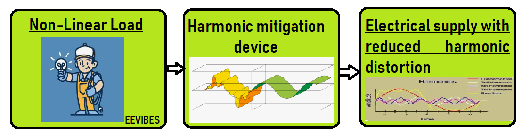
In a practical installation, the mitigation device is usually connected in parallel with the nonlinear load or installed in series with the relevant power circuit, depending on its design.
For example, an active power filter connected in parallel measures the load current and identifies its harmonic components. A power electronic converter then injects compensating currents that oppose those harmonics. This reduces the harmonic current drawn from the upstream electrical supply.
Passive filters operate differently. They use combinations of inductors, capacitors, and sometimes resistors to provide a suitable filtering path for selected frequencies.
The objective is to reduce harmonic distortion without compromising the stability, protection, or normal operation of the electrical installation.
Types of Harmonic Mitigation Devices
Several technologies are used to reduce harmonic distortion. The most suitable choice depends on the load characteristics, harmonic spectrum, system voltage, operating conditions, and cost.
1. Passive Harmonic Filters
Passive harmonic filters consist of passive electrical components, primarily inductors and capacitors, arranged to attenuate selected harmonic frequencies.
These filters are often tuned to dominant harmonics, such as the 5th or 7th, although broadband and high-pass configurations are also used.
Working principle:
A passive filter creates a frequency-dependent impedance. At its designed frequency, it provides a favorable path for the targeted harmonic current or attenuates the harmonic component through its filter response.
Advantages:
- Relatively simple construction
- No high-frequency switching converter required
- Potentially economical for stable, predictable loads
- Can provide reactive power compensation when appropriately designed
Limitations:
- Performance depends on system impedance and load conditions
- May require separate designs for different harmonic frequencies
- Can interact with network impedance and create resonance
- May be bulky at lower frequencies
Applications: Industrial rectifiers, motor-drive installations, and facilities with relatively stable harmonic profiles.
2. Active Power Filters
Active power filters (APFs) use power electronic converters and control algorithms to compensate for harmonic currents or voltages.
They are especially useful when nonlinear loads change frequently or produce several significant harmonic components.
The most common configuration for current harmonic mitigation is the shunt active power filter.
How a Shunt Active Power Filter Works
A shunt active power filter is connected in parallel with the nonlinear load. Current sensors measure the load current, while a controller estimates the harmonic component that needs to be compensated.
A power converter, typically using semiconductor switches such as IGBTs or other suitable devices, generates a compensating current. This current opposes the load’s harmonic current so that the upstream source supplies a current closer to a sinusoidal waveform.
The simplified relationship is:
[
i_s(t)=i_L(t)-i_c(t)
]
where:
- (i_s(t)) = source current
- (i_L(t)) = nonlinear load current
- (i_c(t)) = compensating current injected by the filter
The equation assumes that (i_c(t)) is defined in the direction that subtracts the unwanted load-current components from the source current.
An active power filter can also be designed to compensate for reactive current and improve power factor, subject to its current and voltage ratings and control strategy.
Advantages:
- Can compensate for multiple harmonic orders
- Responds to changing load conditions
- Can reduce current distortion dynamically
- May provide reactive power compensation
Limitations:
- Higher initial cost than many passive solutions
- Requires control electronics and power semiconductors
- Has finite current compensation capacity
- Produces switching losses and requires appropriate thermal management
Applications: Manufacturing plants, data centers, commercial buildings, and installations with varying nonlinear loads.
3. Hybrid Harmonic Filters
Hybrid harmonic filters combine passive filtering elements with active power electronic compensation.
The passive section can handle selected harmonic components economically, while the active section compensates for residual harmonics or variations in the load.
Advantages:
- Can reduce the active converter’s required rating
- May offer a cost-effective solution for complex harmonic profiles
- Can provide broader mitigation than a single tuned passive filter
- May reduce the risk of some passive-filter limitations when properly designed
Limitations:
- More complex design and coordination
- Requires careful analysis of network impedance
- Performance depends on the interaction between active and passive sections
Applications: Large industrial facilities, high-power converters, and installations requiring a combination of economical filtering and adaptive compensation.
4. Line Reactors and DC-Link Chokes
Line reactors are inductors installed in series with an electrical supply or converter input. DC-link chokes are installed in the DC link of certain power electronic systems.
These components can smooth current variations and reduce harmonic currents under appropriate conditions. They are often used with variable-frequency drives and rectifier-based equipment.
Advantages:
- Relatively simple and robust
- Can limit current transients
- May reduce harmonic current levels
- Often suitable for retrofitting compatible equipment
Limitations:
- Usually cannot eliminate harmonics on their own
- Cause voltage drop and additional losses
- Effectiveness depends on the converter and system design
Applications: Motor drives, industrial rectifiers, and power conversion equipment.
5. Phase-Shifting Transformers and Multi-Pulse Rectifiers
Multi-pulse rectifier systems use multiple rectifier bridges supplied by appropriately phase-shifted transformer windings. Under suitable conditions, the harmonic currents from different bridges partially cancel each other.
Common arrangements include 12-pulse and 18-pulse rectifiers.
Advantages:
- Can substantially reduce characteristic input current harmonics
- Suitable for certain high-power industrial applications
- May be effective for relatively stable converter loads
Limitations:
- Transformers can be large and expensive
- Requires compatible rectifier and transformer configurations
- Actual performance depends on load balance and system conditions
Applications: Large motor drives, industrial DC power supplies, and high-power conversion systems.
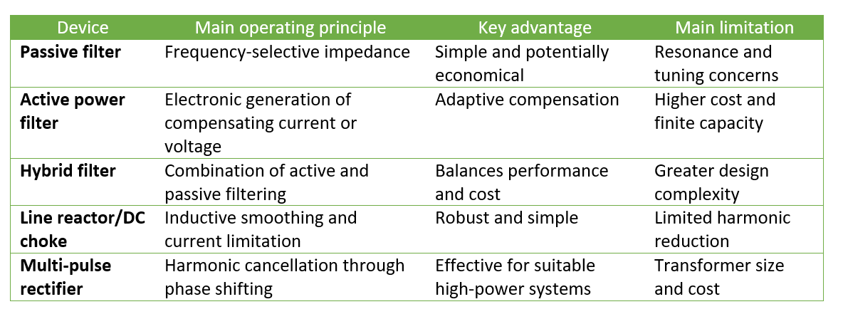
Comparison of Harmonic Mitigation Devices
What Is an Active Power Filter Panel Module?
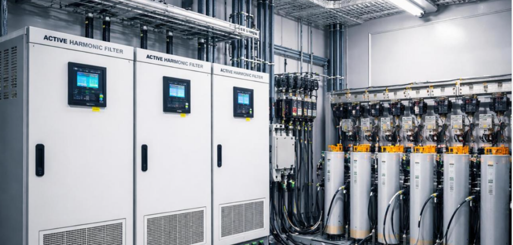
An active power filter panel module is a power electronic assembly used to reduce harmonic distortion in an electrical installation. Depending on the product, it may be installed in a dedicated panel or integrated into a larger power quality system.
Commercial active filter systems commonly include some combination of the following:
- Power electronic converter
- Control and monitoring circuitry
- Current measurement sensors
- DC-link energy storage components
- Coupling inductors or other interface components
- Cooling arrangements
- Protection and communication features
The controller monitors electrical current and generates compensation commands. The power converter then injects the required compensating current into the system.
Some commercial systems also provide reactive power compensation, phase balancing, or neutral-current compensation. These capabilities vary by product and configuration and should be verified against the manufacturer’s technical documentation.
When selecting an active filter panel module, engineers should evaluate rated voltage, compensation current, system frequency, harmonic spectrum, installation environment, cooling requirements, protection coordination, and compatibility with the existing electrical network.
Problems Caused by Harmonics in Electrical Systems
Excessive harmonic distortion can cause several operational and economic problems.
1. Transformer and Cable Overheating
Harmonic currents can increase RMS current and additional losses in conductors and transformers. Some harmonic frequencies can also increase winding eddy-current and other frequency-dependent losses.
2. Reduced Power Quality
Voltage distortion can affect the operation of sensitive electrical equipment, particularly when the supply impedance is significant and harmonic currents produce distorted voltage drops.
3. Capacitor Bank Problems
Capacitor banks can interact with system inductance, creating resonance conditions that amplify harmonic currents or voltages. This may lead to overheating, nuisance tripping, or premature capacitor failure.
4. Protective Device Nuisance Tripping
Distorted waveforms and elevated RMS currents can affect the behavior of some protective devices. Whether a device trips depends on its design, settings, and the actual electrical conditions.
5. Increased Electrical Losses
Additional harmonic current can increase resistive and frequency-dependent losses, reducing system efficiency and increasing operating costs.
6. Neutral Conductor Overloading
In three-phase, four-wire systems, triplen harmonics—such as the 3rd, 9th, and 15th—can add in the neutral conductor under common balanced nonlinear-load conditions. This can create significant neutral-current and thermal concerns.
A properly designed mitigation strategy can reduce these risks, although its effectiveness must be confirmed through engineering analysis and measurement.
Applications of Harmonic Mitigation Devices
Harmonic mitigation technologies are used across many sectors where nonlinear loads affect power quality.
Industrial manufacturing: Facilities using VFDs, welding equipment, rectifiers, and automated production lines.
Commercial buildings: Offices, shopping centers, hospitals, and large buildings with electronic lighting and power conversion equipment.
Data centers: Installations with UPS systems, servers, cooling equipment, and other electronically controlled loads.
Renewable energy: Solar inverter installations and other grid-connected power electronic systems.
Electric vehicle charging: Charging stations and depots with multiple power converters operating simultaneously.
Water treatment and pumping: Facilities using large motor drives and variable-speed pumping systems.
Railways and transportation: Selected traction and auxiliary power installations that use nonlinear power conversion equipment.
The required solution depends on the electrical network, load profile, harmonic measurements, and operational objectives.
Standards for Harmonic Mitigation
Electrical engineers should consider relevant power quality standards when designing or evaluating harmonic mitigation systems.
Two widely referenced standards are:
- IEEE 519: Addresses harmonic control in electric power systems, including recommended practices and limits evaluated at the applicable point of common coupling.
- IEC 61000 series: Covers electromagnetic compatibility, including harmonic emissions, compatibility levels, measurement, and assessment methods across relevant parts of the series.
The applicable limits depend on the standard, equipment category, installation conditions, system voltage, and point of assessment. A filter should not be selected solely on the basis of a single generic THD percentage.
Engineers should verify the current edition and relevant clauses for the specific application and jurisdiction.
How to Select the Right Harmonic Mitigation Device
Selecting a suitable device requires a structured assessment rather than choosing a product based only on its rated capacity.
- Measure the existing harmonic distortion. Record current and voltage harmonic spectra under representative operating conditions.
- Identify the nonlinear loads. Determine whether the main contributors are VFDs, rectifiers, UPS systems, EV chargers, or other equipment.
- Evaluate system impedance. Assess the possibility of resonance, particularly when passive filters or capacitor banks are present.
- Determine the mitigation target. Establish the required harmonic reduction, reactive power compensation, or other power quality objective.
- Compare available technologies. Consider passive, active, hybrid, and converter-based solutions.
- Check electrical ratings. Verify voltage, current, frequency, short-circuit conditions, thermal limits, and protection requirements.
- Consider future expansion. Account for expected changes in the load profile and additional equipment.
- Verify performance after installation. Repeat measurements under comparable operating conditions to confirm that the desired improvement has been achieved.
For installations with rapidly changing loads or multiple harmonic orders, an active or hybrid filter may be appropriate. For predictable loads dominated by selected harmonics, a properly engineered passive solution may be more economical.
Conclusion
Harmonic mitigation devices play an important role in maintaining power quality, reducing unwanted harmonic distortion, and improving the reliability of electrical installations. Passive filters, active power filters, hybrid systems, line reactors, and multi-pulse rectifiers each offer different advantages depending on the application.
Active power filters are particularly useful when harmonic currents vary with operating conditions, while passive filters can provide an economical solution for stable and well-characterized loads. Hybrid systems combine these approaches, and other techniques may be appropriate for specific converter installations.
The most effective solution begins with accurate measurements, identification of harmonic sources, and an assessment of the electrical network. By selecting the right technology and verifying its performance, engineers can reduce harmonic-related problems and improve the operation of modern power systems.
For electrical engineering students and practicing engineers, understanding harmonic mitigation is an important step toward designing efficient, reliable, and power-quality-compliant electrical installations.