Introduction
Bluetooth wireless technology is a short range radio technology that is designed to fulfill the particular needs of wireless interconnections between different personal devices, which are very popular in today’s society. Its development started in mid 1990’s, when a project within Ericson Mobile Communication required a way to connect a keyboard to a computer device without a cable. The wireless link turned out to be useful for many other things, and it was developed into more generic tool for connecting devices. A synchronous mode for voice traffic was added and support for up to seven slaves was introduced. In order to gain momentum for the technology and to promote acceptance, the Bluetooth Special Integrate (SIG) group was founded in 1998. The group consists of many companies from various fields. By joining forces, the SIG members have evolved the radio link to what is now known as Bluetooth wireless technology.
Trade-offs
Bluetooth wireless technology is targeting devices with particular needs and constraints. The main issues are, as with all battery-powered consumer electronics, cost and power consumption. Consequently, certain design trade offs have been made between the cost and power consumption on one side and overall performance on the other. For instance, some of the specified requirements for the radio are chosen to be so relaxed thar it is possible to implement a rather cheap one-chip radio with very few external components (such as filters).
In a radio environment, where communications links are set up on request rather than by default (without the need for a centralized infrastructure, as in cellular networks) and where any node is able to communicate with any other node, networking is usually called ad hoc networking or ad hoc connectivity. Ad hoc connections impose special requirements for the security functionality for the system. Bluetooth wireless technology is particularly well suited for ad hoc usage scenarios.
Bluetooth Protocol Stack
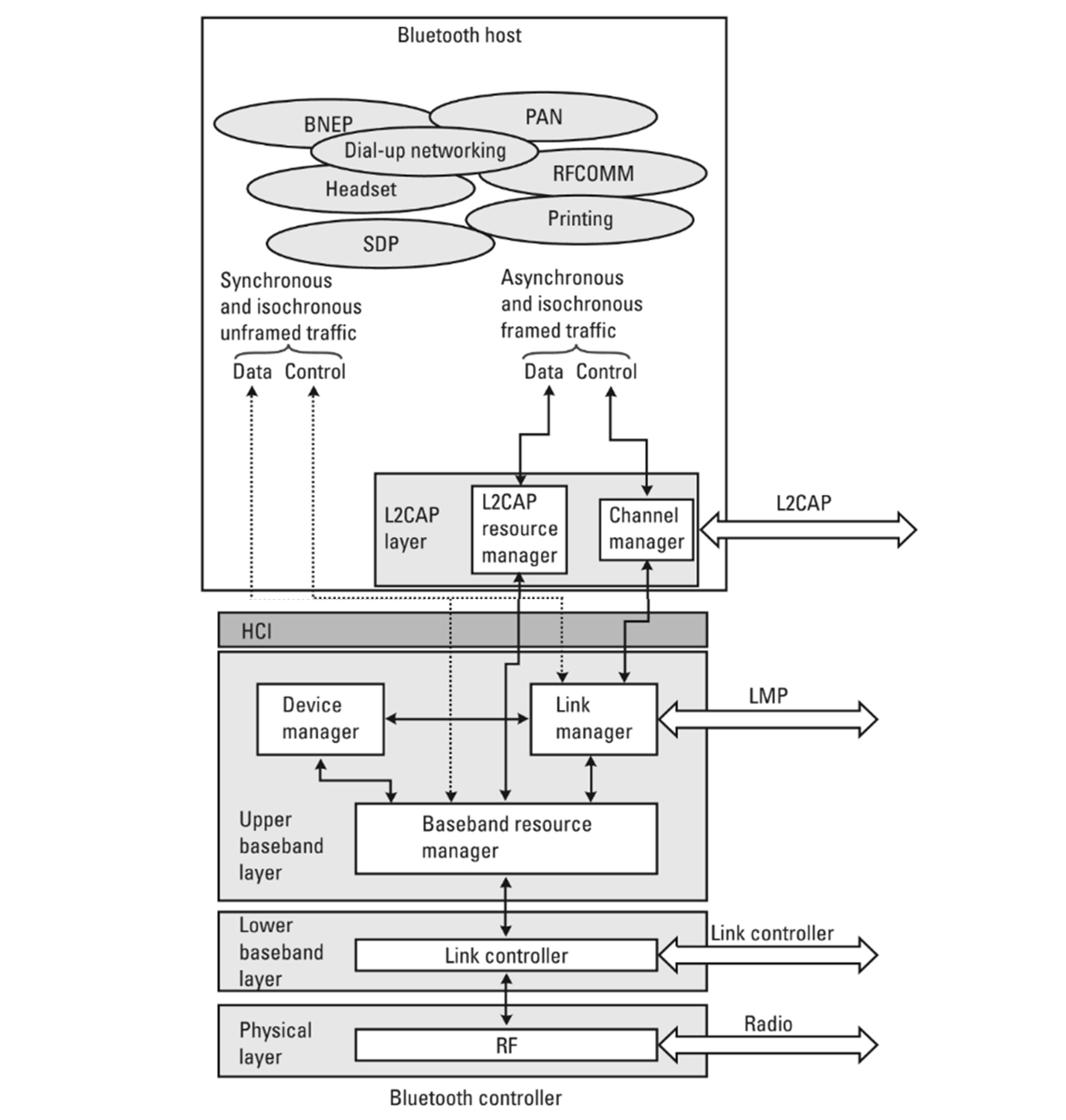
The Bluetooth system stack is shown in the figure below. At the bottom is the physical layer, which is basically the modern part. This is where the radio signals are processed. The functional limits on sensitivity (range) and interference rejection are set by the radio front end (noise figure) and filters implemented in this layer.
Above the physical layer is the baseband layer, which is divided into lower and upper parts. In the following, we will not differentiate between these, but simply refer to them as baseband. it is at this layer that packets are formatted: creation of headers, checksum calculations, retransmission procedure, and , optionally, encryption and decryption are handled. The link controller (LC) is the entity that implements the baseband protocol and procedures.
Bluetooth links are managed by the link manager (LM). The devices set up links, negotiate features, and administer connections that are up and running using the link manager protocol (LMP).
Large chunks of user data need to be performed into smaller units before they can be transmitted over the Bluetooth link. it is the responsibility of the logic link communication and adaptation protocol (L2CAP) to take care of this. At this layer it is possible to ask for certain quality-of-services (QoS) values one would like to reserve for the link.
In many cases, the Bluetooth functionality is to be integrated into a host entity that has computational power but lacks the radio part. For this purpose, Bluetooth modules handling only the lower layers exist. The entity handling the functionality of these layers is sometimes referred to as the Bluetooth controller. For instance, a laptop that is capable of handling higher protocol layers can embed a module that handles radio, baseband, and L2CAP. In such a setup, the higher layers that are implemented in the host entity will communicate with the lower layers of the module through the host controller interface (HCI).
Physical Layer
Bluetooth radio operated in the license-free and globally available industrial, scientific, and medical (ISM) band at 2.4GHz. Because the ISM band is free, Bluetooth has to share this frequency band with many other systems. various wireless communication systems operate in this band (besides Bluetooth, IEEE 802.11b, most notably). Other systems may be defined in the future. One other common device emitting radio frequency power in this band is found in almost all homes: the microwave oven. Even though the vast majority of the radiation is absorbed by the food inside the oven, some of it leaks and will appear outside as interference. Actually, the leakage may be as much as 1000 times more powerful than the signal one tries capture, so this interference cannot be neglected. Fortunately, the interference is not there all the time (loosely speaking, the radiation cycle follows the frequency of the power supply) and is not over the entire frequency system (approximately 15 to 20 MHz of the frequency band and is affected by the microwave oven).
All in all, it is very hard to predict what kind of interference to expect in the ISM band. To combat this, Bluetooth deploys a frequency hopping (FH) spread spectrum technology. There are 79 channels used, each with a bandwidth of 1 MHz. During communication. the system makes 1,600 hops per second every spread over these channel according to a pseudorandom pattern. The idea is that if one transmits on a bad channel, the next hop, which is only 625 us later, will hopefully be on a good channel. In general, faster hopping between frequencies gives more spreading, which improves on protection from other interference. however, the improved performance comes at the cost of increased complexity. The hopping rate chosen for Bluetooth is considered to be a good trade-off between performance and complexity.
The signal is transmitted using binary Gaussian frequency shift keying. The raw bit rate is 1 Mbps, but due to various kinds of protocol overhead, the user data rate cannot exceed 723Kbps. Following regulatory bodies indifferent parts of the world, the maximum transmit power is restricted to 1mW (or equivalent to 20 dBm). It is expected that this will give a range of 100m at line of sight. Another power class, where the output power is restricted to 1mW (0dBm), is also defined. Radios of this power class are more common in handheld devices, and they will have a range of 10m at the line of sight.
One should notice that the specification defines the sensitivity level for the radio such that the raw bit error rate (BER) 10^-3 is met, which translates into the range number given above within the specified link budget.it is around this raw BER that a voice link without error-correcting capabilities becomes noticeably distorted. This is a major reason for the choice of the BER 10^-3 as a benchmark number for the radio specification. However, for data traffic, Bluetooth applies cyclic redundancy check (CRC) as well as optional error correction codes. Thus, of the receiver detects a transmission error, it will request a retransmission. The result is that when operating at BER 10^-3 (and even worse, to some extent), a data link will function quite well anyway. Depending on the payload lengths and packet types, the decrease in throughput may even be unnoticed by the user, This of course, good for the users, but also for potential eavesdroppers, who may be able to choose a position beyond the specified for their purposes.
Baseband
Addressing and setting up connections
Each Bluetooth radio comes with a unique, factory preset 48-bit address. This address, known as the Bluetooth device address (BD_ADDR), constitutes the basis for identification of devices when connections are established, Before any connection, can be setup, the BD-ADDR of the addressee must be known to the side that initiates a connection. For first time connection, this is accomplished by having the initiating side collect the device addresses of all nearby units and then individually address the one of interest. This step is known as inquiry procedures. naturally, once this has been done, the information gathered can be reused without the need for another inquiry at the next attempt to one of the known devices.
the first step in finding the other devices is to send an inquiry message. This message is repeatedly transmitted following a well-defined, rather short hop sequence of length 32. Any device that wants to be visible to others (also known as being discoverable) frequently scans the inquiry hop sequence for inquiry messages, This procedure is referred to as inquiry scan. A scanning device will respond to inquires with its BD_ADDR and the current value of its native clock. The inquiry message is anonymous and there is no acknowledgement to the response, so the scanning device has no idea who made the inquiry, nor if the inquirer received the response correctly.
This inquirer gathers response for a while and can, when so desired, reach a particular device through a page message . This message is sent on another length 32 hop sequency determined from the 24 least significant bits of the BD-ADDR of the target device.
A device listens for page messages when it is in the page scan state. The phase of the FH sequence is determined from the device’s native clock. The paging device has knowledge of this from the inquiry response; thus is it possible for the paging device to hit the correct frequency of the paged device fairly quickly. As already has been stated, the inquiry part can be bypassed when two units have set up a connection before and want to connect again. If a long time has passed since the previous connection, the clock of the device may have drifted, causing the estimate of the other unit’s native clock to be inaccurate. The only effect of this is that the connection set-up time may increase because of the resulting of their respective phase in the page hop sequence.
When a page response is received, a rough FH synchronization has been established between the pager and the paged device. By definition, the pager is the master and the paged device is the slave. Before the channel can be setup, some more information must be exchanged between the devices. The FH sequence, the timing, and the channel access code (CAC) are all derived from the master device. In order to fine tune the FH synchronization, the slave needs the BD_ADDR and the native clock of the master. This information is conveyed in a special packet sent from the master to slave. With all information at the slave side, the master and slave can switch from the page hopping sequence (defined by the slave) to the basic channel hopping sequence determined by the master’s parameters.
packet Structure of Bluetooth
A baseband packet consists of an access code, a packet header, and the payload. The access code, which comes first in each packet, is used to trigger and synchronize the receiver. Each piconet uses a unique access code derived from the BD_ADDR of the master. Thus, by inspecting the access code, a receiver can determine if a packet is for another piconet. In that case, processing the rest of the packet can be aborted, which will help it save some power.
The packet header is used to address individual slaves of a piconet. For this purpose, a 3-bit field denoted by logical transport address (LT_ADDR) is used. To increase the robustness of the packet header, it is encoded with a rate R=1/3 repetition code(i.e., each bit is repeated three times).
User data is carried by the payload. The length of this field can vary depending on the type of traffic–from zero bytes up to 339 bytes (plus 4 bytes of payload header and CRC).
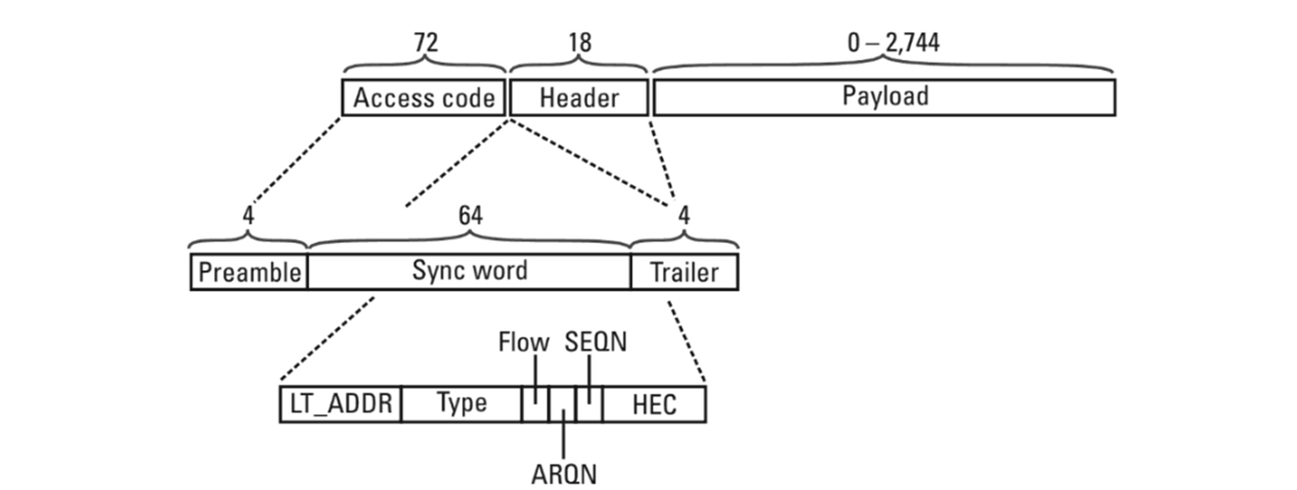
A baseband packet may occupy up to 1,3, or 5 slots, depending on its type. This allows for having symmetric data rates in the forward and reverse directions without the overhead penalty that one-size would cause.