Introduction to Printed Circuit Board (PCB)
How many types of Printed Circuit Boards are manufactured? In this article, you will come to know the basics of Printed Circuit Board Design and Manufacturing. Printed Circuit Boards (PCBs) are an integral part of electronics. They provide a means for electronic components to be mounted and connected electrically or soldered to the board, while providing protection from dust and other contaminants that might cause short circuits. This article will introduce you to printed circuit boards, their purpose in electronics, and how they work.
Printed Circuit Boards (PCB) are found in many electronics devices. They are often used to connect electronic components together, and they can be designed for a variety of uses. Printed circuit boards come with their own set of advantages and disadvantages, but they are still very commonly used today. In this article, we will discuss the basics about printed circuit boards so that you have the knowledge to fully understand them!
Printed Circuit Boards, or PCBs, are a type of electronic circuit board that has been printed onto a thin layer of flexible material. One of their most common uses is in the field of electronics where they carry out many different tasks such as connecting electrical components together and providing pathways for electric current to flow through.
Types of Printed Circuit Board (PCB)
Before starting to know about Printed Circuit Board Design and Manufacturing lets first see how many types of PCBs are there in market. The Types of Printed Circuit Board article is a great resource for anyone with questions about the different types of circuit boards that are available.
Printed circuit boards (PCBs) have been in use since the 1940s and they continue to be important in industries such as aerospace, defense, automobiles, and medical devices.
Choosing the right type of Printed Circuit Board (PCB) for your project can be a daunting task. There are many types to choose from, and each one has its own advantages and disadvantages. In this post we will go over some of the most common Types of PCBs, including both their benefits and drawbacks. We hope that by the end you’ll have a better understanding of what Types work best in different situations!
There are four major PCB types:
- single-sided
- double-sided
- multilayer or thick film
- and flexible circuits
Single-sided PCBs contain only one layer on both sides of the board while double sided PCBs have two layers per side. Multilayers or thicker films can be either single sided or double sided but require more material than thinner ones because there is no cutting process involved when manufacturing.. Choosing the right type of Printed Circuit Board (PCB) is a crucial step when designing any circuit. The PCB can be an integral part of the design, and choosing the wrong one could lead to production delays or even product recalls.
Single Sided PCBs
Single sided Printed Circuit Boards are becoming more popular in the manufacturing industry. Sigle sided PCBs are a much easier to manufacture, which makes them much cheaper when compared with double sided boards. Sigle sided boards also have many other advantages that make them the preferred choice for many manufacturers.
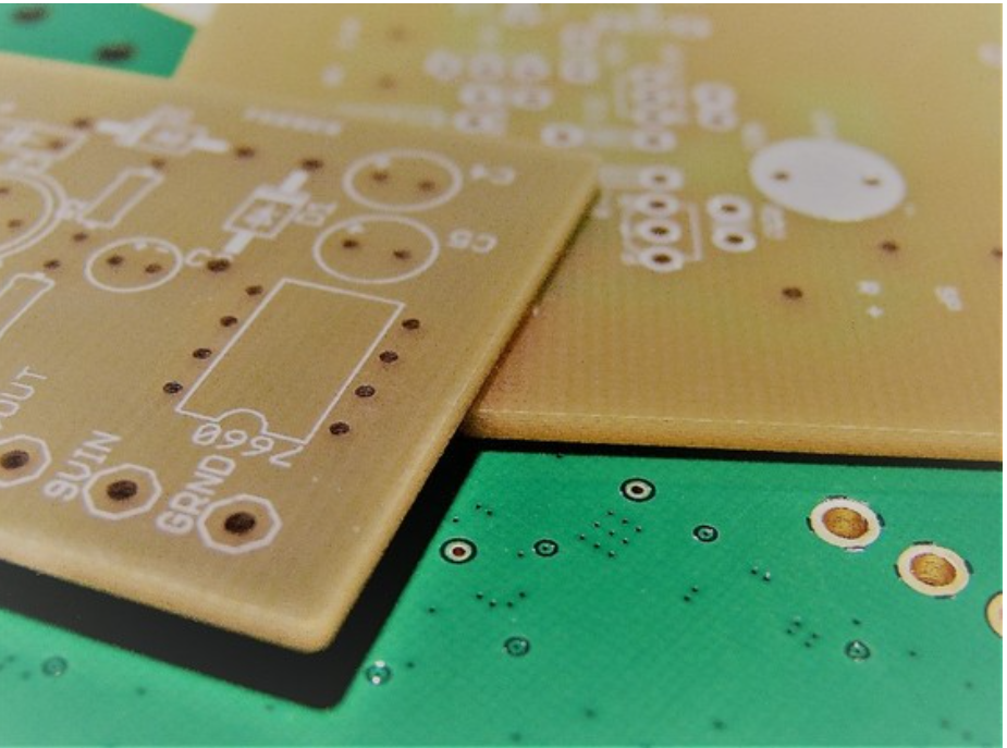
Single sided PCBs are the most common type of printed circuit boards. They consist of one layer, which can be either FR4 or Rogers material with copper traces on both sides. Electrically, it has two conductive planes separated by an insulating substrate. Single-sided PCBs are typically used for low volume production runs because they are easier to manufacture and debug than double-sided ones, but they do have limitations in terms of routing length and component density.
Sigle sided Printed Circuit Boards (PCBs) are used in many different industries. They can be found in cars, boats, heavy equipment and even space stations! Sigle sided Printed Circuit Boards (PCBs) provide a number of benefits to manufacturers including:
– Increased production rates
– Reduced manufacturing costs
– Improved reliability
double-sided PCBs
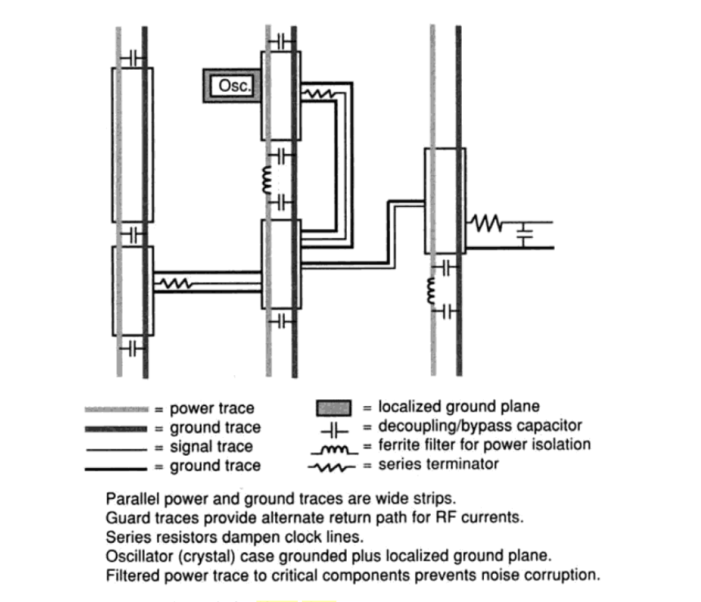
A double-sided PCB is a printed circuit board that has both the top and bottom layers etched onto it. This double sided PCB is typically used when there are many components on the board, or when they need to be in close proximity with one another. Double-sided boards can also offer greater ground plane isolation than single-sided boards because of their use of plated through holes in all layers.
With a double-sided PCB design you can save on material costs by cutting down on board space. Double sided boards also provide more flexibility for placement of components that need to be mounted at an angle or sometimes in hard-to-reach areas. You’ll find that these boards are even easier to assemble with component leads running along both sides of each board. This saves time spent trying to figure out which lead is connected to what hole in PCB Assembly!
What are multilayer or thick film PCB?
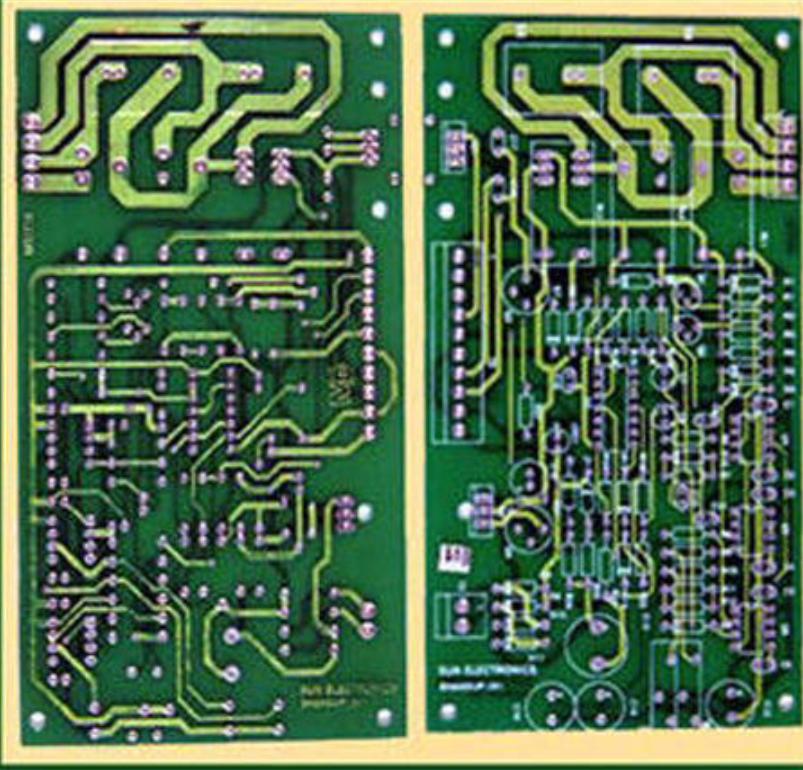
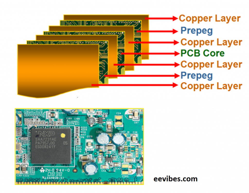
A multilayer PCB is one of the most popular circuit board designs. The multilayer PCB has all the components on one side and then alternates copper layers with insulating layers, which are laminated together to form an electrical connection between each layer. A multilayer PCB can be made in single or multistage construction. Single-stage multilayer boards have two or more metal planes that sandwich their component side while multistage boards use four levels of metal plane sandwiches with alternating dielectric material separating them.
The thickness of a printed circuit board (PCB) is determined by how many layers it contains, which determine its rigidity and weight, but also its cost.
Multilayer refers to the number of layers in a printed circuit board, while thick film is an older technology for making multilayer boards. Multilayers are typically made by laminating thin copper foil onto one side of a sheet of fiberglass-reinforced epoxy resin laminate (FR4) with adhesive and then rolling it into a cylinder. The multilayer can be finished on both sides if desired, but this is more expensive than single sided finishing with FR4. Thick films were originally developed as an inexpensive way to build multilayered boards when FR4 was scarce during World War II and later improved with the development of new materials.
Flexible Printed Circuit Boards
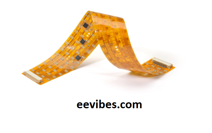
A flexible Printed Circuit Board (PCB) is a PCB designed for flexible substrates. Flexible PCBs are typically fabricated on flexible materials such as plastics and polyester sheets. These flexible printed circuit boards provide circuit designers with an alternative to rigid PCBs, which can be difficult to use in some applications due to board warping or bending resulting from uneven heat distribution and thermal expansion and contraction of the substrate material.
The flexible Printed Circuit Boards (PCBs) market is projected to grow at a CAGR of over 8% during the forecast period. The flexible PCBs are flexible, light weight, high density and can be used in different industries such as automotive electronics, medical devices and other infrastructures where space constraints exist. Flexible PCBs offer unique benefits which cannot be achieved by rigid circuits boards.
The flexible Printed Circuit Boards (PCBs) are flexible boards that can be bent or curved, but still maintain the circuitry pattern. They are flexible enough to be placed over a surface and attached with adhesive. This type of PCB is used where specific shapes are needed for their circuit design, such as in flexible displays. Flexible PCBs have many benefits including being lightweight, thin, durable and more flexible than rigid boards.
Software for designing PCBs
The Softwares used for designing Printed Circuit Boards (PCBs) are varied in nature. However, they all have one thing in common: they help to increase the efficiency of PCB design process. The Softwares used for designing Printed Circuit Boards (PCBs) can be broadly classified into two types: those that provide a graphical interface and those that do not. Softwares that provide a graphical interface offer various features such as interactive drawing tools and simulation modules which reduce the time required for circuit board design. Softwares without a GUI, on the other hand, require you to type commands or use your mouse to draw circuits manually on the screen.
Softwares for designing PCBs are different from one another, each software has its own features and is suited for a specific function. Softwares like Eagle CAD, KiCad, OrCAD, AutoCAD can be used to design PCBs with their respective functions.
printed circuit board manufacturers
Printed Circuit Board Design and Manufacturing: Printed circuit board manufacturers are a critical component of the electronics industry. They provide printed circuit boards for a wide variety of products, including automobiles and medical devices. The printed circuit boards they produce can be used to keep track of inventory, connect power sources to various components, or perform other vital functions in electronic systems. These printed circuit boards may be manufactured with copper wiring or fiber optic cables that carry signals from one end to another. In order to create printed circuits for these types of boards, manufacturers must use sophisticated computer-controlled equipment that is capable of producing very precise designs and patterns using materials such as copper foil sheets or photoresist films.
Printed circuit boards or PCBs are printed circuits that have been manufactured with a printed pattern of copper foil and an insulating layer, which is then etched away to leave behind the printed patterns. Here at Springboard Manufacturing, they manufacture printed circuit boards for many industries including medical devices, telecommunications equipment, computers and consumer electronics.
List of others Printed Circuit Board Design and Manufacturing is given below:
Also read here
https://eevibes.com/engineering-projects/which-arduino-to-buy/