Introduction to LCD
In this article, I have explained how to interface LCD with PIC18f4550 and PIC16F877A microcontroller? LCD also known as liquid displays are widely used these days for displaying characters, numbers, and graphics. They are more advanced displaying devices as compared to simple LEDs or Seven Segment displays. They are also used because of the following reasons:
- The declining prices of LCDs.
- Ease of Programming.
- They have the latching ability.
- Incorporation of refreshing controlling sets CPU free to refresh it.
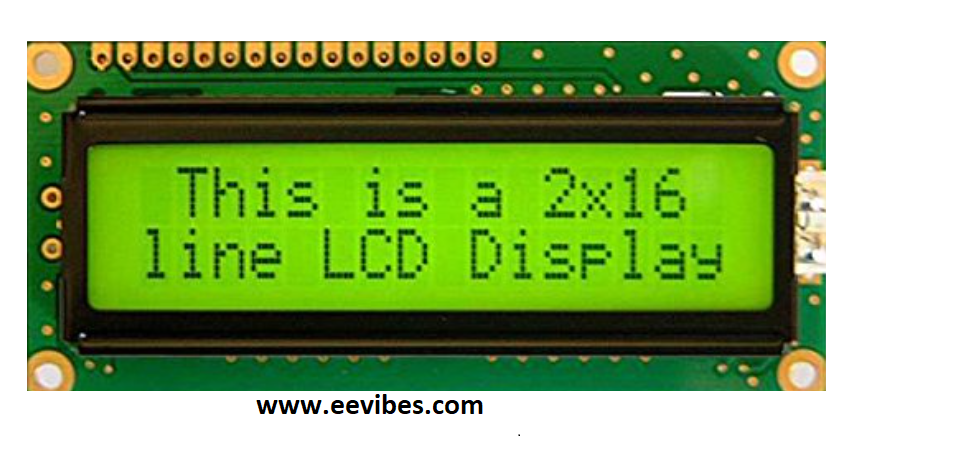
There are different manufacturers of LCDs and they do come in many styles. Some of the LCDs are are 16×2 size, some are 20×2 etc.
Uses of LCDs
A 16×2 LCD, or 16 by 2 Liquid Crystal Display, is a popular and versatile display choice for many electronic projects. Here are some of its common uses:
- Displaying Text and Numbers: This is the most basic and widespread use. With 16 characters per line and 2 lines, it can show essential information like sensor readings, time, status messages, or simple menus.
- User Interfaces: In combination with buttons or rotary encoders, a 16×2 LCD can be used to create menus for user interaction. This allows users to control devices or browse options.
- Informative Displays: In DIY projects or hobbyist electronics, a 16×2 LCD can display data from sensors or microcontrollers. This can be useful for things like weather stations, thermometers, or data loggers.
- Custom Characters: While it primarily displays text, some 16×2 LCDs allow creating custom characters. This enables showing icons, symbols, or special characters that enhance the information display.
Pin description of LCD
There are 8 data lines (8 pins) for displaying the characters/numbers on LCDs. On these data lines microcontroller will be sending data for display. There are control pins: RS (Register Select), R/W (Read/write: W is an active low pin. It means write operation can be performed by sending 0 logic to it). E (enable Pin).
What is the RS pin of LCD?
Register Select (RS) is used for selecting the internal register of LCD. There are two internal registers corresponding to this pin.
- Data Register
- Command Register
Command Register
If RS=0 then command register is selected. The command register is used for issuing commands to LCD. These commands are used for configuring the LCD. The configuration involves the selection of the internal matrix, clearing data of LCD, cursor blinking and positioning the cursor etc. Here is the list of the commands that can be used for configuring the LCD.
| Hex Code | Command instructions |
| 1 | Clear display scree |
| 2 | Return home |
| 4 | Decrement cursor |
| 6 | Increment cursor |
| 5 | Shift display right |
| 7 | Shift display left |
| 8 | Display off, power off |
| A | Display off, cursor ON |
| C | Display ON, cursor OFF |
| E | Display ON, cursor blinking |
| F | Display OFF, cursor blinking |
| 10 | Shift cursor position to left |
| 14 | Shift cursor position to right |
| 18 | Shift the entire display to the left |
| 1C | Shift the entire display to the right |
| 80 | Force cursor to the beginning of the 1st line |
| C0 | Force cursor to the beginning of the 2nd line |
| 38 | 2 lines and 5X7 matrix |
Data Register
If RS=1 then data register is selected. In order to send the data for display we will set RS=1.
R/W= If R=0 it means writing operation is being performed on the LCD for displaying the data. It is an active low pin as explained above. If we want to program the LCD for displaying the data by monitoring the busy pin (D7) of LCD then we will be reading its state by setting R/W=1.
Enable pin
This pin is used for latching the data on data lines of LCD. In order to display a character on LCD it needs to be latched for a small duration. This is done by sending a high to low pulse on enable pin. The duration of this pulse should be around 150 msec.
Vcc/Vdd pin of LCD
For powering up the LCD, we need to provide +5V on Vcc or Vdd pin.
Vss pin
It is grounded.
Vee
This pin is used for controlling the contrast of LCD display. We will connect a variable resistor on this pin for controlling the contrast.
| Pin Number | Pin Name | Description |
| 1,2,3 | Vss,Vcc,Vee | Ground, Power Supply +5V, Contrast control |
| 4 | RS | RS=0 (command Register)
RS=1 (Data Register) |
| 5 | R/W | R/W=0 (Write Operation)
R/W=1 (Busy status test) |
| 6 | E | Enable pin for latching the data on data lines |
| 7-14 | DB0-DB7 | Data Lines |
| 15 and 16 | Anode and cathode pins | For controlling backlight of LCD |
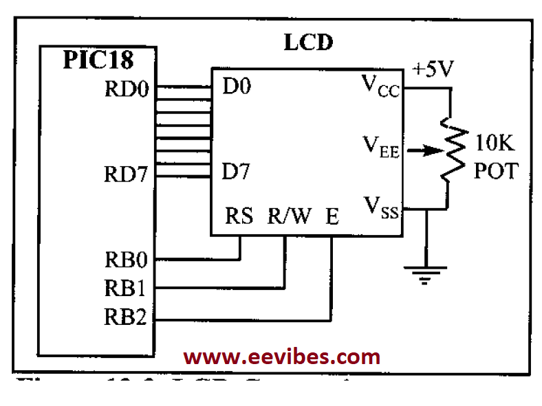
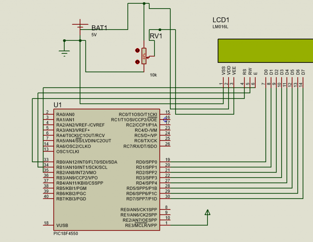
LCD connection with PIC microcontroller
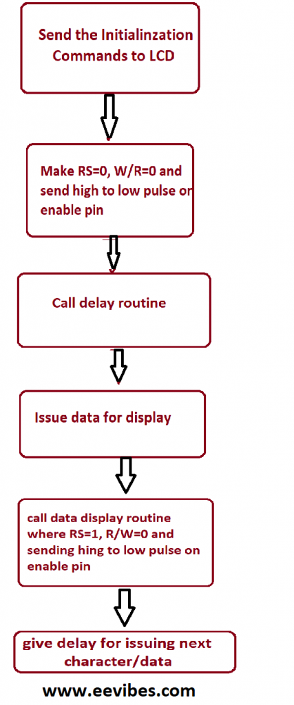
Flow chart for connecting/interfacing the LCD with PIC18f4550 Microcontroller
Code for Interfacing LCD with PIC18F4550 Microcontroller in Assembly Language
In this code PORTD is connected with data lines of LCD and first three pins of PORTB are used for control signals RS, R/W and Enable
PORTB.0 (RS)
PORTB.1 (R/W)
PORTB.2 (E)
The following code is run on MPLAB software.
#INCLUDE<P18F4550.INC>
ORG 0X00
R1 EQU 0X04
R2 EQU 0X05
R3 EQU 0X06
R4 EQU 0X07
R5 EQU 0X08
R6 EQU 0X09
CLRF TRISD
CLRF TRISB
BCF PORTB,2
CALL DELAY
MOVLW 0X38
CALL COMMAND
CALL DELAY
MOVLW 0X0E
CALL COMMAND
CALL READY
MOVLW 0X01
CALL COMMAND
CALL READY
MOVLW 0X06
CALL COMMAND
CALL READY
MOVLW 0X85
CALL COMMAND
CALL READY
MOVLW A’H’
CALL SHOW
CALL READY
MOVLW A’I’
CALL SHOW
YOU BTG PORTB,0
BRA YOU
SHOW
MOVWF PORTD
BCF PORTB,1
BSF PORTB,2
BSF PORTB,0
CALL SDELAY
BCF PORTB,2
RETURN
COMMAND MOVWF PORTD
BCF PORTB,0
BCF PORTB,1
BSF PORTB,2
CALL DELAY
BCF PORTB,2
RETURN
READY SETF TRISD
BCF PORTB,0
BSF PORTB,1
BAC BSF PORTB,2
CALL DELAY
BCF PORTB,2
BTFSC PORTD,7
BRA BAC
CLRF TRISD
RETURN
DELAY MOVLW D’20’
MOVWF R1
L22 MOVLW D’52’
MOVWF R2
L11 MOVLW D’50’
MOVWF R3
HEREA1
NOP
NOP
DECF R3,F
BNZ HEREA1
DECF R2,F
BNZ L11
DECF R1,F
BNZ L22
RETURN
SDELAY MOVLW D’10’
MOVWF R4
L2 MOVLW D’10’
MOVWF R5
L1 MOVLW D’100′
MOVWF R6
HEREA
NOP
NOP
DECF R6,F
BNZ HEREA
DECF R5,F
BNZ L1
DECF R4,F
BNZ L2
RETURN
END
C Language Code for Interfacing LCD with PIC16F877A Microcontroller
Here, is the code written in C language that can compiled on software MikroC pro for PIC.
#define LcdDataBus PORTB
#define LcdControlBus PORTD
#define LcdDataBusDirnReg TRISB
#define LcdCtrlBusDirnReg TRISD
#define LCD_RS 3
#define LCD_RW 4
#define LCD_EN 5
/* local function to generate delay */
void delay(int cnt)
{
int i;
for(i=0;i<cnt;i++);
}
/* Function to send the command to LCD */
void Lcd_CmdWrite(char cmd)
{
LcdDataBus = cmd; //Send the Command nibble
LcdControlBus &= ~(1<<LCD_RS); // Send LOW pulse on RS pin for selecting Command register
LcdControlBus &= ~(1<<LCD_RW); // Send LOW pulse on RW pin for Write operation
LcdControlBus |= (1<<LCD_EN); // Generate a High-to-low pulse on EN pin
delay(300);
LcdControlBus &= ~(1<<LCD_EN);
delay(200);
}
/* Function to send the Data to LCD */
void Lcd_DataWrite(char dat)
{
LcdDataBus = dat; //Send the data on DataBus nibble
LcdControlBus |= (1<<LCD_RS); // Send HIGH pulse on RS pin for selecting data register
LcdControlBus &= ~(1<<LCD_RW); // Send LOW pulse on RW pin for Write operation
LcdControlBus |= (1<<LCD_EN); // Generate a High-to-low pulse on EN pin
delay(300);
LcdControlBus &= ~(1<<LCD_EN);
delay(10000);
}
int main()
{
char i,a[]={“Be Kind :)”};
LcdDataBusDirnReg = 0x00; // Configure all the LCD pins as output
LcdCtrlBusDirnReg = 0x00; // Configure the Ctrl pins as output
Lcd_CmdWrite(0x38); // enable 5×7 mode for chars
Lcd_CmdWrite(0x0E); // Display OFF, Cursor ON
Lcd_CmdWrite(0x01); // Clear Display
Lcd_CmdWrite(0x80); // Move the cursor to beginning of first line
Lcd_DataWrite(‘B’);
Lcd_DataWrite(‘E’);
Lcd_DataWrite(‘ ‘);
Lcd_DataWrite(‘R’);
Lcd_DataWrite(‘E’);
Lcd_DataWrite(‘A’);
Lcd_DataWrite(‘L’);
Lcd_CmdWrite(0xc0); //Go to Next line and display Good Morning
for(i=0;a[i]!=0;i++)
{
Lcd_DataWrite(a[i]);
}
while(1);
}
Manufacturers of LCDs
Optrex is one of the largest manufacturers of LCD. You can easily find datasheet of LCDs from their website. Other famous manufacturers are:
- digikey.om
- jameco.com
- elexp.com
- bgmicro.com
For alphanumeric displays, 16×2 is recommended and it is easy to configure.
Hardware Connection of LCD with PIC16f877A Microcontroller
How to interface LCD with PIC16F877A microcontroller is explained in the following video.
Lab Manual for LCD and Keypad Interfacing
Also read here