Introduction to Counters:
What are the Different Types of Counters? The output of the counter, a digital device, has a quantified state based on the submissions of the clock pulses. You can count the number of pulses using the counter’s output. Counters classically include a flip-flop configuration and can be also synchronous or asynchronous. In a synchronous counter, each flip-flop receives a solo clock i/p, whereas in an asynchronous counter, the flip-flop receives the clock signal from the adjacent one.
Types of Counters
The output of the counter has a specified state grounded on the applications of the clock pulses. You can tally the number the counter’s output. Counters classically include a flip-flop configuration (synchronous or asynchronous).
In a synchronous counter, each flip-flop takes a single clock whereas in an asynchronous counter, the flip-flop receives the clock signal. The microcontroller’s applications need counting of external events accurate internal time delay generation. Computers and digital systems regularly use these incidences.
Temporal Counters
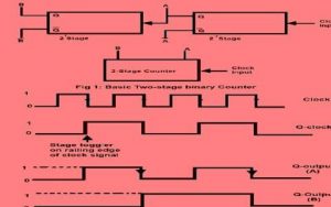
a 2-bit asynchronous counter. Only the clock i/p first flip-flop is linked to the external clock. FF changes its state at the dropping edge of every clock pulse. The change in the i/p clock pulse and a change in the Q o/p of FF0 can never take place exactly at the same time spread delay.. The FFs can therefore not be activated concurrently.
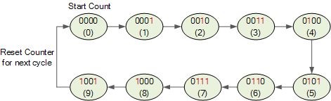
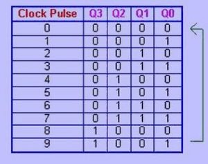
Temporal Decade Counters
Counters with states less than 2n are still also believable. These are made with the number of states in each series in mind. The counter is made to recycle before drifting through all of its states to generate these so-called petite sequences. 10 is a typical modulus for counters with shortened sequences. A decade counter is a counter which has 10 states in its series. Description of the implemented decade counter circuit.
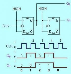
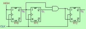
Synchronous Counters
The CLK i/ps of all the FFs are related and triggered by the i/p pulses. All of the FFs instantly shift positions.
Flip-J flop0’s and K inputs are supported to HIGH. The J and K inputs of flip-flop 1 are connected to the flip-flop 0 output (FF0), and the J and K inputs of flip-flop 2 are connected to the output (FF2) of an AND gate that is fed by the outputs of flip-flop 0 and flip-flop 1
Also check
What are the synchronous and asynchronous counters?
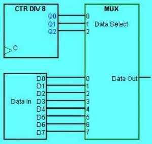
Applications of Counters
The primary multiplexing and digital clock practice for counters. The parallel to serial data conversion logic explained below is the best diagram of a counters.
Ring counter
An exclusive use for the Serial IN OUT Shift register is as a ring counter. The last flip flop result is used as the shift register’s output, which is the only difference between it and the ring counter. hence, ring counter, this outcome is given as an input to the first flip flop. The long-lasting gears of the ring counter are equal to those in the shift register.
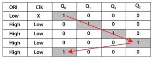
When the pre-set is set to 0, the output is 1. When the strong is set to 0, the output is 0. Since PR and CLR are active low signals they both function at value 0 at all times.
Types of Ring Counter
The ring counter is divided into the two classes:
Straight Ring Counter
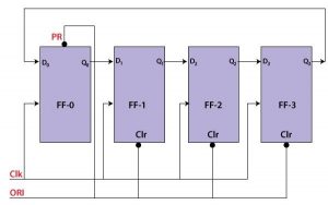
One hot Counter is the term second-hand by the Traditional Ring Counter. The initial flip-flop receives the effect of the earlier flip-flop as input. The first flip flop’s PR input and the following flip flops’ clear inputs.
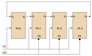
Twisted Ring Counter
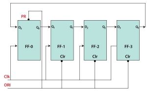
A switch-tail ring counter is pardon the Twisted Ring Counter usages. The result of the previous flip-flop is transmitted to the first flip-flop, just like the straight ring counter. The ORI input is given to all of the flip flops in the perverse ring counter as clear input.
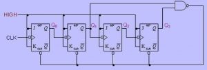
BCD Counter Circuit:
A numerical counter called a BCD counter can count up to 10 if a clock signal is practical.
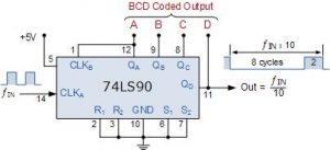
The ability of switching T-type flip flops to function as self-governing divide-by-2 counters was earlier confirmed. The amount of times a specific count preparation has happened can be stored or by a digital BCD counter shaped by joining many toggle flip-flops together in a sequences chain. A clock signal, digital captives can count upward from zero to a desired count value. Reset-ing them resets the counter to zero to start over once the count limit has been reached.
Also read here
- How to Design Counters Using Sequential Circuits?
- What are the CMOS Logic Gates?
- What is the magnitude comparator circuit? Design a 3 bit magnitude comparator circuit
- What are the synchronous counters? Explain with an example.
- what are the half adder and full adder circuits?
- what are the half subtractor and full subtractor circuits?
- How to design a four bit adder-subtractor circuit?
- What are number systems in computer?
- Discuss the binary counter with parallel load? Explain its working with an example
- how to draw state diagram of sequential circuit?
- How to simplify a Boolean function using Karnaugh map (k-map)?
- What are the flip flops and registers in digital design?
- Define fan-in, fan-out, CMOS and TTL logic levels
- what is the Canonical form representation of Boolean function?
- What is difference between latches and flip flops?