How to Design a Four bit Adder-Subtractor Circuit?
In this article you will learn about how to design a four bit adder-subtractor circuit? Every Digital Computer should always execute two arithmetic Operations: addition & subtraction. Multiplication & Division operations become simple if both of these tasks are implemented properly (Multiplication is equivalent to repeated addition, whereas division is equivalent to repeated subtraction). Take into account the process of trying to add multiple binary numbers, that is the basic operations executed by a computer system. The four fundamental addition operations for multiple binary numbers which are single bit, are as follows:
- 0 + 1 = 1
- 1 + 0 = 1
- 0 + 0 = 0
- 1 + 1 = (Carry)1 0
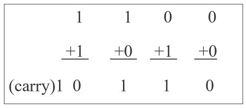
Every Digital Computer should always execute two arithmetic Operations: Every binary addition during first 3 operations yields a total of one bit, namely, either zero or one. However, the output of the 4th addition operation (with inputs of One and one) is 2 binary numbers. here lower significant bit usually referred to as ‘Sum Bit,’ whereas higher significant bit has been referred to as ‘Carry Bit.’
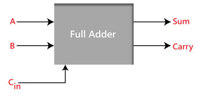
A full adder within Digital Logic
The full adder is an added that takes three inputs &generates two outputs as a result. The first 2 inputs typically A & B, with the third being a C-IN input carry. Output carry generally labelled as C-OUT, whereas normal output labelled as S, that stands for SUM.
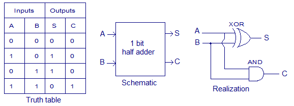
Half adder:
A half adder is a type of combinational arithmetic circuitry that uses two numbers addition and outputs an S, sum bit, as well as a C, carry but. The S (sum bit) is the result of the XORing of A & B, and also the C (carry bit) is the ANDing of A & B, if A & B, seem to be input bits.
4 Bit Adder and Subtractor
Binary Adder-Subtractor comprises a digital circuit that can perform basic arithmetic of binary integers in the same circuit. The binary result of a control signal determines the operation to be executed. It’s among the ALU‘s, arithmetic logic unit elements
XOR Gate, Full Adder, and Binary Addition & Subtraction, are all prerequisites for this circuit.
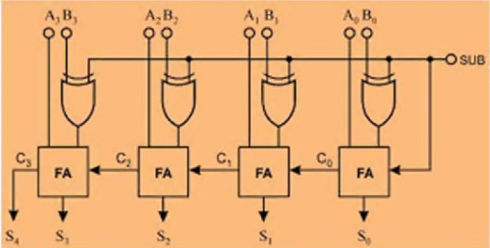
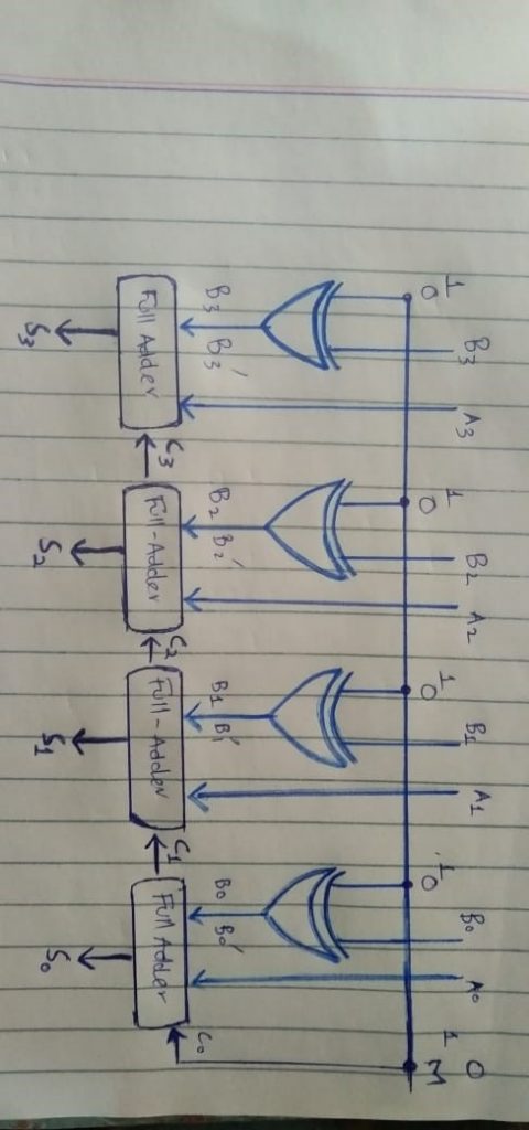
Designing: A single basic binary adder may do both addition & subtraction tasks. As illustrated in the diagram underneath, a binary circuit may be created by combining an Ex-OR gate alongside every full adder. 4-bit parallel adder and 4-bit parallel subtractor shown below has multiple 4 bit inputs labelled ‘A3 A2 A1 A0’ & ‘B3 B2 B1 B0’.
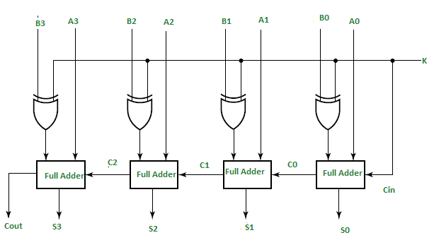
The carry input of the of the full adder’s least significant bit is linked to the mode input control line labelled as k. The kind of execution, either addition and otherwise subtraction, is determined by such a control line.
If k equals to 1, circuit is just a subtractor, but when k equals to zero, it is then converted to an adder. XOR gate has 2 inputs, only one of which being Linked to the B, the other to the input k. Whenever k = 0, B Ex-ORed 0 results in B. Next, full adders perform addition of B & A with carry input 0, resulting in addition operation.
- If M = 1, the B Ex-ORed Zero produces the B complement, as well as the carry input becomes 1. As a result, inputs of complemented B are added with A, then One is added via input carry, nothing more than an operation of 2’s complement. As a result, the operation of subtraction is carried out.
- First Adder: The 1st full adder includes a control line as one of its direct inputs (input carry Cin).
- Second Adder: Within full adder, the input A0, A’s least significant bit, is explicitly input.
- Third Adder: The XORed of k and B0 is the 3rd input. Sum or Difference, referred to as S0 and Carry (C0) are the outputs generated.
Also see : How to Design a 4 bit Magnitude Comparator Circuit?
Procedure
Finally, as being one of the outputs of the 2nd full adder, C0 gets serially passed. The sum or difference S0 gets stored as the sum or difference’s least significant bit. A1, A2, & A3 constitute as direct inputs to the 2nd, 3rd, and 4th full adders, respectively. The 3rd input would be the B1, B2, B3 XORed K to the 2nd, 3rd, and 4th full adders. Carry C1 and C2 get serially passed as inputs towards the consecutive full adder. C3 will become the sum or difference’s total carry. S1, S2, and S3 are recorded in order to build the outcome with S0.We employ n full adders to create an n-bit adder-subtractor.
Also read here about fan-in and fan-out
What is the difference between fan-in and fan-out? Examples
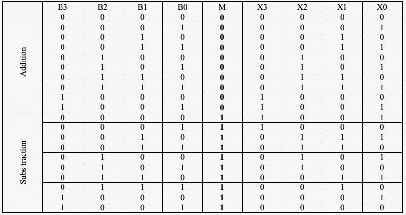
Truth Table of 4-bit Adder-Subtractor Circuit
Adder Circuit
First of all, what is a binary adder? It is a type of digital circuit that usually adds binary numbers using logic gates. In ordinary addition of binary numbers we use only two bits at a time in order to add them i.e we add 1 and 0 at a time or we add 0 and 1 only at a time, moreover we add 1 and 1 or 0 and 0 at a time. But in this system we directly add the whole binary number to another whole binary number at a time with the help of arithmetic circuits. There are two types of adders which are full-adders and half-adders as discussed below:
Full-adders:
It is used for the addition of significant digits.(carry)
The logic gates which are used in Binary full-adders are And gate, OR gate and EXOR gate. In practical life, the applications of full adders are that they are used in digital processors.
Half-adders:
It is used for addition of Least significant digits. The logic gates involved in half adders are EX OR gate and AND gate. Half adders are practically used in digital measuring devices like calculators.
For reading more about Full-adder and Half-adders check:
How to design Half adder and Full adder circuits?
Subtractor Circuit:
It is a digital circuit used for subtraction of binary numbers using logic gates. In this we add (2’s compliment and 1) on the number from to be subtracted. For example we have to subtract A from B, We do A+ (2’s compliment of B+1). Two types: Half-subtractor and Full-subtractor.
Full subtractor:
It is the circuit in which subtraction of two bits is done by borrowing. There are three inputs and two outputs.
Half-Subtractor:
The half subtractor is used to subtract two binary . There are two inputs and two outputs on this device. This circuit is used to subtract two binary values, A and B, that are both single bits. The half subtractor has two output states: ‘diff’ and ‘borrow.’
Four bit Adder-Subtractor
Basically it is a digital circuit which does both addition as well as subtraction itself. This circuit works using an EX-OR gate, binary addition and subtraction, Full adder.
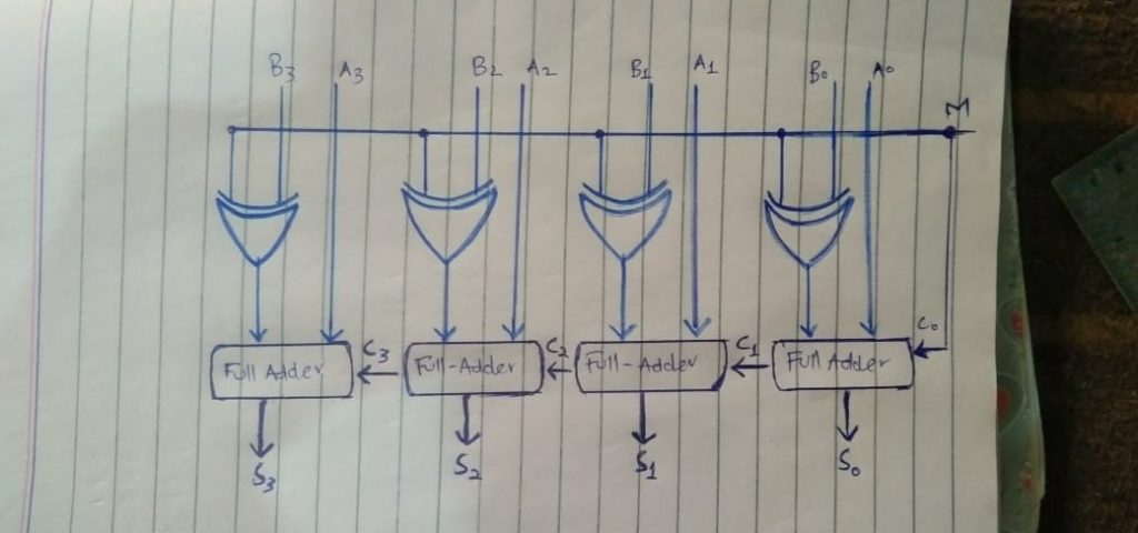
We will need four full adders. Supplying them inputs respectively, A0, A1, A2, A3 for first adder, second adder, third adder, and fourth adder. Now the second input for adders would be output of EX-OR gates, Same as input A, There would be attached four EX-OR gates with all adders respectively. As we all know that this EX-OR gate will have two inputs. The first input of this EX-OR gate would be named as B, and as done previously
We will name B0, B1, B2, B3 respectively. And the second input to this EX-OR gate is what we are providing it to be ‘M’ input which would be the second input of the EX-OR gates and which would be same for all EX-OR gates. This M will decide whether we are performing addition operation or subtraction operation. And Beside all this the 3rd input we are going to provide is to be known as the carry or borrow, which would be the same ‘M’. In case of addition it would be carry while in case of subtraction it would be borrow.
So in addition operation this carry is given to the full-adder and the full adder output would be sum S0 (at the first adder) and carry C1(from the first full adder). And the carry generated would be propagated to the next full adder. Similarly, next full adder will generate sum and generate carry to next full adder, and so on to all full adders.
But if it would be a subtraction operation then instead of sum we would be having difference and instead of carry we would be having borrow. So this is our circuit.
Example of adder-subtractor circuit
Lets see its working with an example:
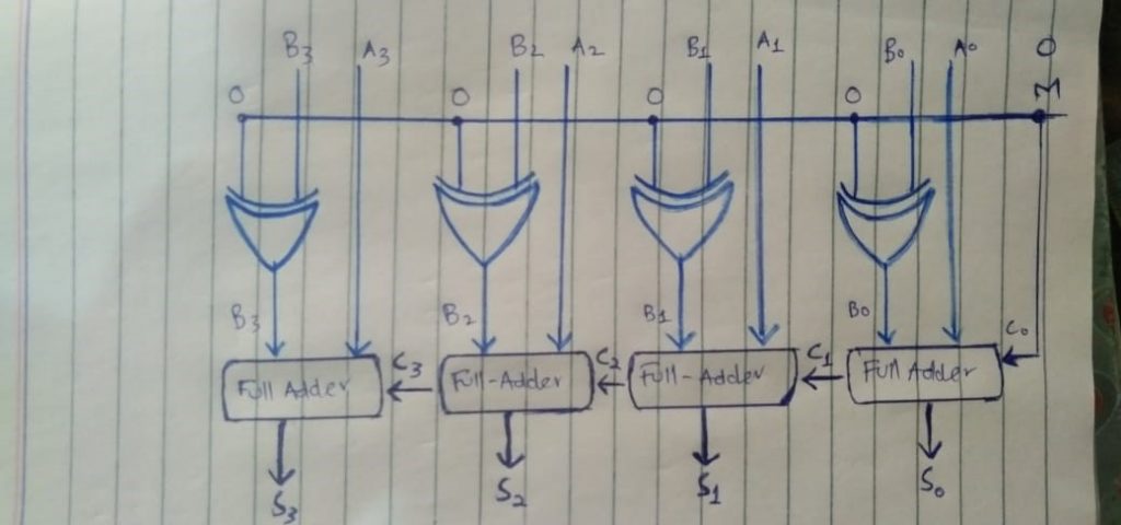
If we provide ‘M’ to be ‘0’ all the EX-OR gates will have one fixed input ‘0’ and carry ‘C0’ would also be ‘0’, If we talk about another input of EX-OR gate that is B, So as per truth table of XOR gate if we XOR any value with 0 then it would be same as that value. So as per truth table or XOR ‘0’ XOR ‘ B0’ we would be having output ‘0’. O XOR b1 we would be having B2, 0 XOR B3 we would be having B3. In simple input to this XOR gate would be B. On the other hand on carry side Carry would be 0 because we had fixed M as 0. So in a nutshell the formula for Sum becomes: M=A+B (by taking M=0).
Now considering M to be 1, So all inputs of XOR would be 1, as per truth table of XOR if we XOR any value with 1 it would always be compliment of that value. So B0 XOR 1 would be B0’(B0 compliment). B XOR 1 would be B1’ and so on.
so if we provide M to be 1 then input to full adder becomes compliment of B So it becomes A + B’ + 1. Which is nothing but our subtraction. So formula for subtraction is M= A+B’+1 by (taking value of M 1)
Working of 4-bit adder subtractor circuit
Role of C (carry) and V (overflow) bit in Adder-Subtractor Circuit
Consider the advanced version of 4-bit adder-subtractor circuit which comes with carry (C) bit and overflow (V) bit. The role of C pin is to determine the overflow in the unsigned numbers. If C=1, then there is a carry out in case of addition (indicating unsigned overflow) or a borrow in during subtraction.
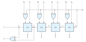
V bit is used for indicating the signed overflow. Let us consider the case for understanding the concept of overflow. Basically overflow occurs when we add or subtract two n-bit numbers and the resultant is of n+1 bit.
We know that the range of 4-bit unsigned numbers is 0 to 15 and range of 4-bit signed numbers is -8 to 7. For getting the idea of how to determine the range, check this link.
Now, assume the case when we want to add two numbers A=1000, B=0101. If we treat both numbers as unsigned, then A is equal to 8 in decimal and B= 5 in decimal. To see how we perform number systems conversion, check the link.
If you will perform A+B bit wise
1000
0101 +
_________
1101
_________
There will be no carry out. Now if you convert this binary to decimal you will get the result is equal to 13. So unsigned overflow did not occur. Now consider the other case when A=1001 (9) and B=0111 (6). When you will perform bit wise addition, you will see there is a carry out (C) from the last full-adder. Which will indicate the unsigned overflow. Since 9+7=16 which is actually out of range of 4-bit numbers. If you will consider the 5-bits (10000) including the carry bit C, then the result is correct otherwise 4-bit sum (0000) shows the wrong result. V=0 in this case.
Role of C and V pin in adder-subtractor circuit
Now again assume same inputs A=1001 and B=0111. But this time we are going to perform the subtraction A-B considering A and B as signed numbers. As we know that when we treat numbers as signed, the MSB represents the sign of the number. If MSB=1 then the bit combination represents the negative number and when MSB=0 then a positive number is stored. So in our case A=-ve number and B=+ve (7).
We can see what number A represents by taking its 2’s complement.
1112
1001 –
________
___0111__
so it actually represents -7. When you will perform subtraction using the adder subtractor circuit, you will see V=1 and also C=1. This actually indicates there was a borrow in during subtraction (while treating them as unsigned numbers) and V=1 which actually shows a signed overflow occurred as explained in my video lecture given below. Since (-7)-(+7)=-14 which is actually out of range of 4-bit numbers. That’s why you will need total 5-bits for representing the correct answer.
How to determine the overflow of signed and unsigned numbers?
Overflow in 4-bit adder-subtractor circuit
Looking for some PhD scholarships, click here
Related topics:
- half adder and full adder circuit design
- half subtractor and full subtractor circuit design
- How to simplify a Boolean function using Karnaugh map (k-map)?
- What are the flip flops and registers in digital design?
- What is the magnitude comparator circuit? Design a 3 bit magnitude comparator circuit
- How to design a 4 bit magnitude comparator circuit?
- how to represent Boolean functions in class of reversible logic circuits?
- What are number systems in computer?
- Number System Conversions – Briefly Explained
- How to design Half adder and Full adder circuits?
- What are the decoders? how are they different from encoders?
- What is binary arithmetic? How to add, subtract, multiply and divide two binary numbers?
- How many hundreds are there in 1000?
- What are the synchronous counters? Explain with an example
- what are the BCD and binary ripple counters?