What is the Magnitude Comparator Circuit?
In this article you will get the idea of what is the magnitude comparator circuit? A combinational circuit which compares two binary or digital numbers to find out whether the binary number is equal, greater than, less than the other binary number is called Magnitude Comparator Circuit. In this circuit we have 2 inputs A and B. There are 3 outputs available:
A=B
A>B
A<B
These comparators are used in Microcontrollers and CPU’S to perform data comparison, register and arithmetic operations. They are used in many devices. Every automatic device is based on magnitude comparators. Without magnitude comparator the automatic devices are useless. Comparators are the basics for working of the automatic devices. In these circuits different gates are used to perform the specific actions. There are different kinds of gates used in comparators. In our daily life magnitude comparators are used in different devices and different things. They are the main thing in working of automatic devices. In comparators there are inputs which comparator or process these inputs on the basis of information given to the comparator. There could be 2 or more inputs.
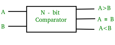
Block diagram of magnitude comparator circuit
The basic diagram of magnitude comparators is given below:
Types of Magnitude Comparators:
- 1-bit magnitude comparator
- 2-bit magnitude comparator
- 3-bit magnitude comparator
- 4-bit magnitude comparator
- 8-bit magnitude comparator
1 bit Magnitude Comparator
The 1 bit magnitude comparator is a simple comparator circuit which compares the magnitude of two numbers that can be represented with a single bit. It must be noted that only one of the output out of 3 outputs can be at logic 1.
1 bit comparator truth table
The following table shows the 1 bit comparator truth table. When A=0 and B=0 then A=B=1 because their value is same. Same is true for A=B=1. At this point, it can be noticed that A<B and A>b both have 0 logical value. When A=1 and B=0, then A>B=1 and when A=0 and B=1 then A<B=1
| A | B | A=B | A<B | A>B |
| 0 | 0 | 1 | 0 | 0 |
| 0 | 1 | 0 | 1 | 0 |
| 1 | 0 | 0 | 0 | 1 |
| 1 | 1 | 1 | 0 | 0 |
Boolean Expression for 1 bit Comparator
Now, lets drive the Boolean Expression for all these three functions. You can do that by ORing those minterms where the function value is equal to 1.
Here is the Boolean Expression for 1 bit magnitude comparator circuit.
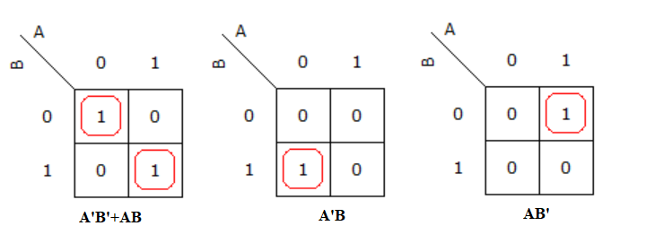
F(A=B)=A’B’+AB = (A⨁B)’
F(A<B)= A’B
F(A>B)=AB’
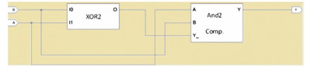
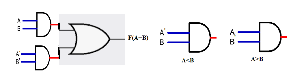
1 bit Magnitude Comparator Circuit Diagram
2-BIT MAGNITUDE COMPARATOR Truth Table
In the 2 bit magnitude comparator, we compare two numbers that are represented by two bit. Assume that A1 A0 and
B1 B0 are two numbers that we want to compare. Since the total number of input bits are 4 so 24 are the possible combinations of input which is equal to 16. The following truth table shows the relationship between inputs and the outputs.
| A1 | A0 | B1 | B0 | A=B | A>B | A<B |
| 0 | 0 | 0 | 0 | 1 | 0 | 0 |
| 0 | 0 | 0 | 1 | 0 | 0 | 1 |
| 0 | 0 | 1 | 0 | 0 | 0 | 1 |
| 0 | 0 | 1 | 1 | 0 | 0 | 1 |
| 0 | 1 | 0 | 0 | 0 | 1 | 0 |
| 0 | 1 | 0 | 1 | 1 | 0 | 0 |
| 0 | 1 | 1 | 0 | 0 | 0 | 1 |
| 0 | 1 | 1 | 1 | 0 | 0 | 1 |
| 1 | 0 | 0 | 0 | 0 | 1 | 0 |
| 1 | 0 | 0 | 1 | 0 | 1 | 0 |
| 1 | 0 | 1 | 0 | 1 | 0 | 0 |
| 1 | 0 | 1 | 1 | 0 | 0 | 1 |
| 1 | 1 | 0 | 0 | 0 | 1 | 0 |
| 1 | 1 | 0 | 1 | 0 | 1 | 0 |
| 1 | 1 | 1 | 0 | 0 | 1 | 0 |
| 1 | 1 | 1 | 1 | 1 | 0 | 0 |
K-Map for 2-bit Magnitude Comparator When (A=B)
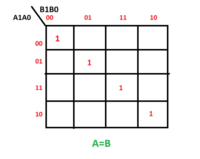
Boolean Function Expression for A=B for 2-bit Magnitude Comparator
F(A=B)=A’1 A’0B’1 B’0+A’1 A0B’1 B0+A1 A0B1 B0+A1 A’0B1 B’0
you can simplify it further by applying the Boolean algebra rules.
K-Map for 2-bit Magnitude Comparator When (A>B )
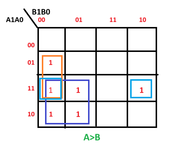
Boolean Function Expression for 2-bit Magnitude Comparator when A>B
F(A>B)=A1B’1+A0B’1 B’0+A1 A0B’0
K-Map for 2-bit Magnitude Comparator when A<B
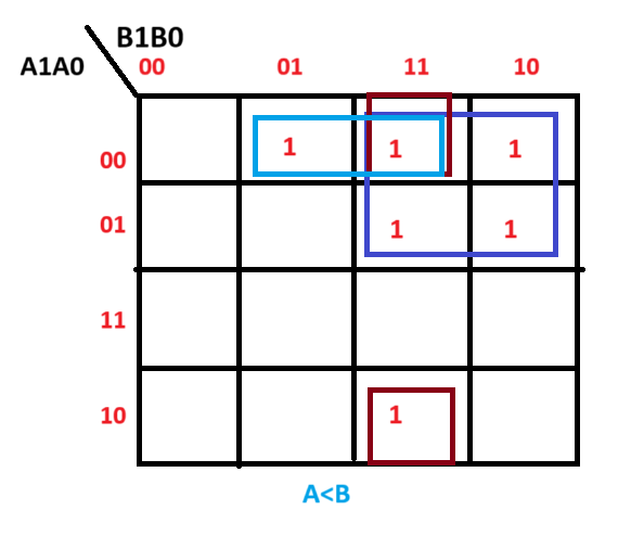
Boolean Function Expression for 2-bit Magnitude Comparator when A<B
F(A<B)=A’1B1+A’1 A’0B0+A’0B1 B0
3-BIT MAGNITUDE COMPARATOR:
A comparator which compare 2 binary numbers having 3-bits and produce the resultant of 3 outputs on the basis of magnitude of given binary numbers is called 3-bit magnitude comparator. 3-input magnitude comparator is more effective than the 2-bit magnitude comparator while it is less effective than the 4-bit and 6-bit magnitude. 3-bit magnitude comparator gives expression which is less complex than the 2-bit magnitude while this expression is complex in the cases of 4-bit and 6-bit and so on.
A 3-bit magnitude comparator compares two 3-bit binary numbers:
where:
are the bits of the first number
(Most Significant Bit-MSB)
, Least Significant Bit (LSB)
.
are the bits of the second number
.
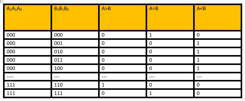
Since we have 3 bits for input variable A and 3 bits for input variable B. Hence the total possible combinations at the input side are equal to 26=64. Here is the compact table for 3-bit magnitude comparator, since it is not possible to write all the possible combinations of inputs.
Also check
How to Design a 4 bit Magnitude Comparator Circuit? Explanation with examples
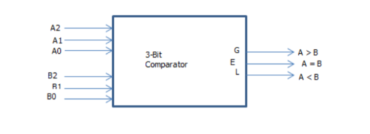
Block diagram of 3-magnitude comparator circuit
The diagram for 3-input magnitude comparator is given below:
Equations:
The equations for 3-bit magnitude comparator are given below:
The equal functions are :
Ao = Bo
Then:
A=B=(Ao’Bo’+AoBo)(A1’B1’+A1B1)(A2’B2’+A2B2)
The output is:
A<B
In the cases of :
A2<B2
A2=B2 then A1<B1
A2=B2, A1=B1 then Ao<Bo
A<B=A2’B2+[(A2’B2’+A2B2)*A1’B1]+[(A2’B2’+A2B2)*[(A1’B’+A1B1)*Ao’Bo]
The output is A>B.
In the case of:
A2>B2
A2=B2 then A1>B:
A2=B2, A1=B1 then Ao>Bo
A>B=A2B2’++[(A2’B2’+A2B2)*A1B1’]++[(A2’B2’+A2B2)*[(A1’B’+A1B1)*AoBo’]
Implementation Using Digital ICs
A 3-bit comparator can be implemented using basic gates, or a dedicated comparator IC like 74LS85, which is a 4-bit comparator but can be adapted for 3-bit comparisons.
Steps to Implement Using Logic Gates
- Use XOR gates to check equality.
- Use AND & OR gates for greater than and less than conditions.
- Connect the outputs to LEDs or display devices to indicate results.
See here:
How to Create a Test Bench for Verilog HDL Module?
TRUTH TABLE:
The truth table of 3-input magnitude comparator is given below:
K-MAP FOR 3-INPUT COMPARATOR: (A, B, C)
The table for min terms of 3-input comparator k-map is given below:
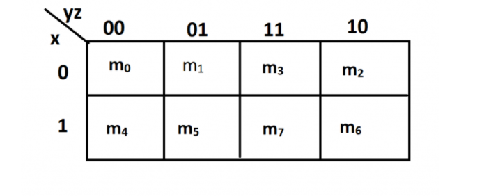
There are 3 inputs A, B, C which will also return in the form of 3 outputs. There are 8 min terms available in this starting from Mo to M7. By using the k-map we can easily design or form truth tables for comparators. The technique of k-map is very easy and simple. There is very less error in k-map method as compared to the Boolean Laws. In his method there is no need of remembering the every rule of Boolean Laws. There are very few steps in this technique to find the expression for our given information.
This technique always results in simple, minimum and easy expression which the user can easily understand and can easily solve it. This technique is only efficient when the method is carried out very precisely. If there is some mistake by the user the resultant expression will not be correct and there could be errors in this expression. So it is very important to carry out the method very carefully and precisely.
When the variables are increased the k-map simplification becomes more complicated. From this we found out that the k-map simplification is only useful when the input variables are only from 3 to 6 variables. Other than that the k-map simplification will result in the form of wrong expression and there will be difficult for the user to understand and solve the expression.
EXAMPLES:
Examples of 3-bit magnitude comparator are given below:
Here F shows the function while A, B, C are the inputs of the function.
EXAMPLE#1

The resulting expression is in the form of B compliment multiply by C and + with inputs A and B.
F=B’C+AB
EXAMPLE #2:

The result is B compliment multiply by C and + by A
F=B’C+AB+AB’
F=B’C+A (B+B’)
F=B’C+A
These are the very good examples of 3-bit magnitude comparators. The resultant expression depends upon how we combine the terms. If we combine the terms vertically the result is different while in case of horizontal combination the result is different than the vertical combination. In each example the method of combining the bits is different than other. In every combination we get an equation of that example. We combine the bits 2 by 2. In some cases we also combine 4 bits. Combining 2-bits gives us a complex equation. While combining 4-bits gives us the less complex equation. We can combine them vertically but also horizontally. It depends on our easiness. Both methods are useful.
How to add User Defined Primitives in Xilinx Verilog HDL Programming?
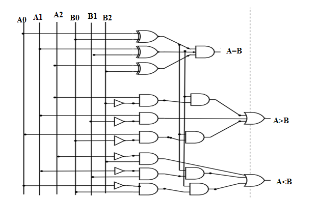
LOGIC DIAGRAM:
The logic diagram of 3-bit magnitude comparator is given below:
Applications of comparator circuit
The basic applications of magnitude comparator are as follows:
- These comparators are used in control applications.
- These are used in applications used for binary numbers presenting variables such as temperature, position etc.
- These comparators are used in our daily life applications.
- These comparators are also used in process controllers.
- These are also used in Servo motor controls.
- These are also used in applications for password verification.
- These are also used in applications for Biometric verification.
- Comparators are also used in CPU’S.
https://www.youtube.com/watch?v=sCZebMUI458
Related topics
- What are the CMOS Logic Gates?
- What are the synchronous counters? Explain with an example.
- what are the half adder and full adder circuits?
- what are the half subtractor and full subtractor circuits?
- How to design a four bit adder-subtractor circuit?
- What are number systems in computer?
- Discuss the binary counter with parallel load? Explain its working with an example
- how to draw state diagram of sequential circuit?
- How to simplify a Boolean function using Karnaugh map (k-map)?
- What are the flip flops and registers in digital design?
- Define fan-in, fan-out, CMOS and TTL logic levels
- what is the Canonical form representation of Boolean function?
- What is difference between latches and flip flops?