What are the synchronous counters? Explain with an example.
What are the synchronous counters? Explain with an example. Unlike ripple and asynchronous counters the synchronous counter is a kind of counter wherein the clock signal is all the while given to each flip-flop embedded in the counter circuit. All the more explicitly, we can say that each flip-flop is set off in synchronism with the clock input. The values of data inputs like T or J and K are examined and a final result of whether to complement a flip-flop is executed .This decision is made at the time of clock edge. It complements the flip-flop when T = 1 or J = K = 1. It remains in the same state when T = 0 or J = K = 0. Synchronous counters are also termed as ‘Simultaneous counters’ on some occasions.
In many ways, the synchronous counters are better than the asynchronous counters. They are mentioned below:
- Easy to design and build compared to asynchronous counter.
- Logic gates control the Count sequence, resulting in very less chances of error.
- It performs simultaneous actions.
- No delay in propagation and no ripple effect are found.
- Operates at a much higher pace than the Asynchronous counter.
Advantages of Synchronous Counters
• Synchronous Counters are easy to design than asynchronous counters.
• No propagation delay associated with it.
• Count sequence is controlled by logic gates, error chances are lower.
• Have faster operations than asynchronous.
• Synchronous counters can be operated on the higher frequencies
Types of Synchronous Counters
There are many types of synchronous counters which we use in daily digital electronics. They are as follows:
- Binary counters
- Synchronous UP counter
- Synchronous DOWN counter
- Binary counter with parallel load
- BCD counters
- Ring counters
- Johnson counters etc.
Designing of Synchronous Counters
The designing of synchronous counters include the following steps:
• Decide the number of flip-flops.
• Excitation table of flip-flops.
• State diagram and circuit excitation table.
• Obtained simplified equations using K-map.
• Draw the logic diagram.
What are the Binary Counters?
A binary counter can be developed from J-K flip-flops by taking the output of one cell to the clock input of the following. The J and K inputs of each flip-flop are placed to 1 to deliver a toggle at every cycle of the clock input. For every two toggles of the first cell, a toggle is created in the subsequent cell, etc. down to the fourth cell. This delivers a binary number equivalent to the quantity of cycles of the input clock signal. This device is now and again called a “ripple through” counter. A similar device is valuable as a frequency divider.
Several D flip-flop circuits are connected to each other in a binary counter. The flip-flops change state with each clock pulse. The output is a binary number that can be used for digital clocks or timers. Usually its design is asynchronous, with the output of one flip-flop connected to the next. When one cell is toggled, the next one is toggle. If there are two toggles, the next cell in the row is toggled. This arrangement is also called a “ripple” counter.
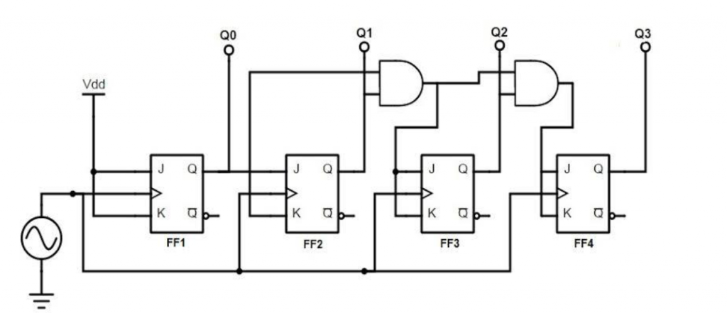
4-bit Synchronous UP Counter
If each J-K flip-flop is enabled to toggle based on whether all the previous flip-flop outputs (Q) are “high” or not, we can get the same count sequence as provided by the asynchronous circuit without the ripple effect. This is because each flip- The flop in this timed circuit will be clocked at exactly the same time.
It provides us with a four-bit synchronous “up” counter. All of the higher order flip-flops stand ready to toggle both the inputs of J and K as “high”. But this happens when the outputs of all previous flip-flops, denoted as “Q”, are “high”.
Otherwise, the inputs of J and K for this flip-flop are both “low”, which in turn puts it in “latch” mode, where it holds its current output state until the next clock pulse arrives.
From the first (LSB), flip-flop has to toggle with each clock pulse, its J and K inputs are connected to Vcc or Vdd, where they are “high” all the time.
The next flip-flop just needs to “recognize” that the output, Q, of the first flip-flop is “high”. This makes it ready to toggle, so no need of an AND Gate.
The remaining flip-flops should be designed to toggle when all lower-order output bits are “high”, therefore an AND gate is needed is this case.
4-bit synchronous up counter start to count from 0 in binary(0000) and increment or count upwards to 15(1111) in binary and then new counting cycle will start after getting reset.
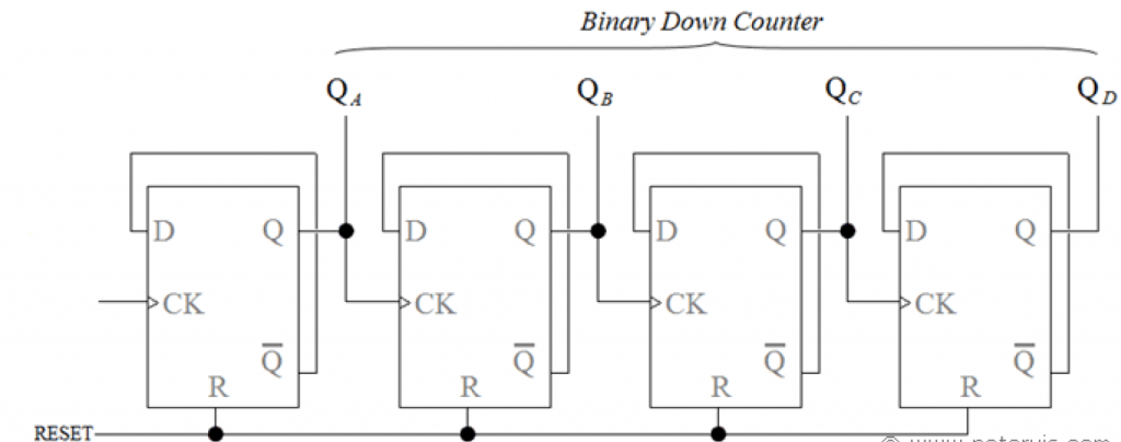
4-bit Synchronous Down Counter
To create a synchronous “down” counter, we need to build the circuit to recognize the appropriate bit patterns that predict each toggle state as it counts down.
Unsurprisingly, when we examine the four-bit binary count sequence, we see that all previous bits are low before a toggle. The sequence if followed from bottom to top.
Since each J-K flip-flop is equipped with output Q and output Q’, we can use the output Q` to activate the toggle mode on each subsequent flip-flop, since each Q` will be “high” when the respective Q will be “low”.
In 4-bit synchronous down counter, the output of flip-flop changes states on the falling edge (1to zero transition) of CLK input which is triggered by Q output of previous flip-flop rather than by the Q output as in the synchronous up counter.
4 bit Up/Down Synchronous Counter
Both synchronous and asynchronous counters are capable of counting up and counting down, but there is another type of universal type of counter that counts in both directions either up or down depending on the state of their input control pin and these are known as Bidirectional Counters. Bidirectional counters are also known as Up/Down Counters.
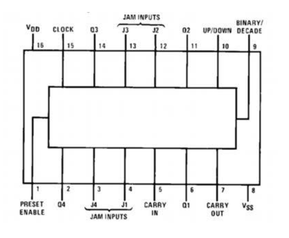
Both synchronous and asynchronous counters are capable of counting up and counting down, but there is another type of universal type of counter that counts in both directions either up or down depending on the state of their input control pin and these are known as Bidirectional Counters. Bidirectional counters are also known as Up/Down Counters.
DIAGRAM:
Binary Counter with Parallel Load
A parallel load counter is simply a circuit that uses reverse gates and flip-flops to generate a sequential count. When we have used it to create a 4-bit binary code count, it is simply called a parallel-loaded 4-bit binary counter. The binary counter with parallel load comprises of two basic circuits. One is the simple binary counter circuit and the other is the parallel load circuit.
We create a binary counter using J-K flip-flop where when both inputs are one, the output toggles, so if the output of a flip flop other than the last one is one and the counter is on, then it was toggled and in the last it takes if all flip flops are one, so a simple binary counter works on this.
Now we apply a parallel load circuit with it. For that we place a parallel load at one of the inputs of all the circuit gates. The second inputs of the gate are connected with the actual input. This process is carried out in such a way that if an input is applied to one gate then its complement will be applied as an input to the gate whose output is connected to the flip flop. The complement of the input J of the flip-flop is applied to the input K of the flip-flop. Now the result of the circuit is that when the load is enabled the applied input is transferred to the resistive circuit.
We can set up a binary counter with parallel load by adding both the above mentioned circuits. Also we have to connect the complement of load and the count with an AND gate plus OR gates are placed before each inputs of the resistive circuit. This keeps the purpose of making circuit intact.
In the designed circuit only one out of “Load” and “Count” can be enabled at a time. In this way when Load is enabled, all of the AND gates pass the value of Load to the resistor circuit. Likewise, enabling the Count will pass the values of Count to the circuit. But on the other hand if both Load and Count are 0 then a memory state is developed by J-K flip flop. In this way a binary counter with a parallel load works.
If we construct a Table consisting the values of Clear, Clock, Load, Count and Function, we will find some interesting results. When the Clear is 0, the Clock, Load and Count also falls, resulting the Function to become 0. When Count has the value of 1 the flip flop moves towards the next binary start. When Load is 1, the value of Count is ignored and the flip flop takes the value of parallel load. When both Clear and Load are 0, the output remains unaffected.
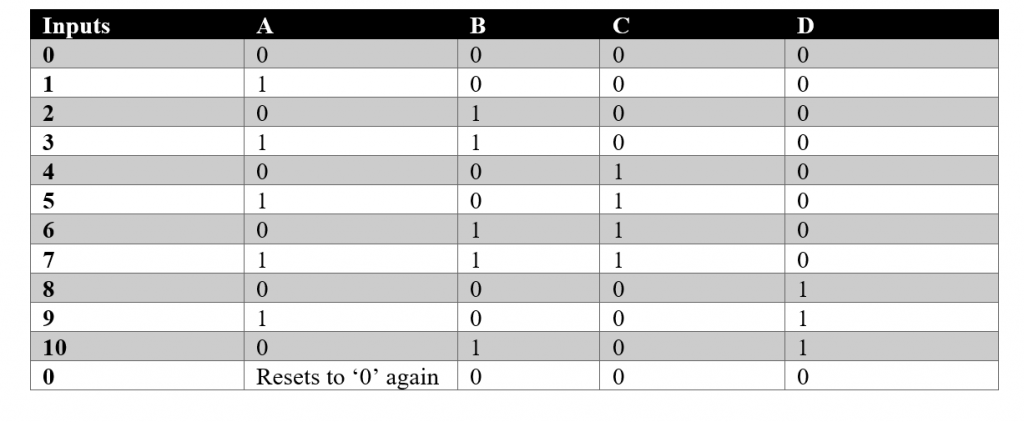
What is the BCD Counter?
A BCD (Binary Coded Decimal) counter, also known as a decade counter, is a serial digital counter designed to count ten digits. It performs the reset process automatically when a new clock input signal is received. Since the counter counts ten unique combinations of the input entered, it is called a decade counter. The values that are counted by a BCD counter are 0, 1, 2, 3, 4, 5, 6, 7, 8, 9, and 10 in binary format. There are also many others. A 4-bit decade counter works like a BCD counter by skipping all 6 of the 24 outputs.
A BCD counter is designed with the help of a J-K flip flop. The outputs of terminals J and K are connected to a logic ‘1’. The clock signal input in each flip-flop is connected to the subsequent flip-flop with the exception of the last flip-flop. The NAND gate output is connected in parallel to the CLR signal for all flip-flops.
The purpose of using BCD counters is to provide accurate representation of decimal number and it’s conversion to and fro. However, there is also a disadvantage of using this counter. It creates the counting delay and the propagation delay during the counting stage.
Truth Table of BCD Counter:
related topics:
- what are the half adder and full adder circuits?
- what are the half subtractor and full subtractor circuits?
- How to design a four bit adder-subtractor circuit?
- What are number systems in computer?
- Discuss the binary counter with parallel load? Explain its working with an example
- how to draw state diagram of sequential circuit?
- How to simplify a Boolean function using Karnaugh map (k-map)?
- What are the flip flops and registers in digital design?
- Define fan-in, fan-out, CMOS and TTL logic levels
- what is the Canonical form representation of Boolean function?
- What is difference between latches and flip flops?