4-bit Binary Counter With Parallel Load
4-bit binary counter with parallel load. A binary counter is simply circuit which comprises of several flip-flop connected in series for each pulse of input the flip-flop toggled and then this given as input to other flip-flop which again toggle it in this way different binary number are generated which we can used for timer and clock. Reversible logic has contemplated as a systematic computing technique having its applications in quantum computing and minimum power computing. All of the Boolean functions can be implemented with the help of reversible gates.
We have proposed a reversible 4-Bit binary counter with parallel load that has lowest complexity and quantum cost comparatively. The first attempt of designing a 4-Bit binary counter with parallel load is the proposed circuit. Counter is basically a register that goes through a predetermined order of conditions.
The reversible gates in the counter are connected in such a way as to produce the prescribed sequence of binary states. This counter receives a 4-Bit data from input and delivers data to D Flip Flop in next cycle. Loading data from input is determined with Load property. The proposed circuit becomes a robust structure by our optimal technique and by the use of these gates. The garbage outputs in the proposed circuit is minimum in numbers and constant inputs in reversible circuit. The proposed circuit is the very first strive and contemplated state for a reversible 4-Bit binary counter. More complex networks could be constructed by the use of proposed circuit.
Modern irreversible logic circuits were more complex circuits than quantum or reversible logic circuits as present. Reversible logic has most well organized characteristic that constructs the circuits as a paradigmatic design. The Conventional circuits if dissimilar with combining of a reversible logic circuit. Most of the reversible logic circuits are synthesized and optimized by genomic algorithms. A reversible logic circuit should use the following characteristics:
- Least number of reversible gates
- Least number of garbage
- Least constant inputs.
- Keep the length of cascading gates short
What is a Counter?
Counter is basically a register that goes through a predetermined pattern of states. Gates in the counter are arranged in such a way as to generate the prescribed pattern of binary numbers. These gates build a counter circuit. Parallel load counter can be used to create any desired count pattern. A 4-bitcounter with parallel load can be helpful to produce a BCD count in two major ways which are given below:
- Using the load input: Overview of this design
- Using the clear input: Overview of this design
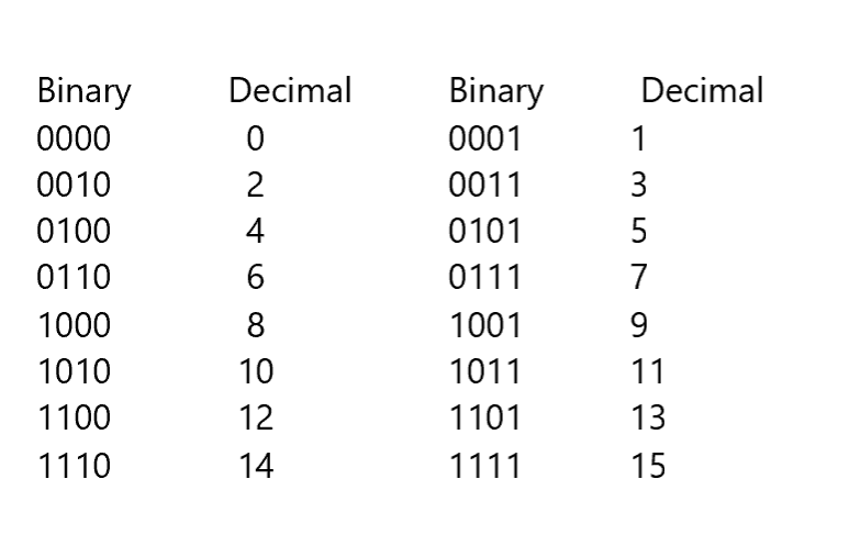
What is Binary Counting?
Binary counting is a system which is basically a conversion of binary numbers into decimal. For the conversion of a binary number to a decimal, we use a simple system. Each digit,
or ‘bit’ of the binary number represents a
power of two. All you want to do a conversion from binary to decimal is added up the applicable powers of 2. In the given case, there is a need to calculate that the binary number 10110111 is equal to 183. Then the figure also indicates that 8 bits combine up what is called a byte. Nibbles are defined as the upper while 4 lower bits of the given byte. Referring to all the bytes and nibbles which are helpful when dealing with other number systems like hexadecimals. The base of hexadecimal system is 16.
How Binary Counter works?
Initially, starting with the study of counters there is few essential information that helpful to be understood. The most essential fact that since the outputs of a given digital chip can only be in one of two further states, it must should apply a different counting system than you are usual to. Commonly, we use a decimal counting system which is defined as a meaning each digit in a number is denoted by one of 10 digits (0-9). In case a binary system, there can only be two digits, 0 and 1.
A computer does not found 0 or 1. It only works on voltage differences. What we call logic 0 to when a computer is set on voltage of 0 volts. What we call logic 1 is voltage of +5 volts. When a logic state alters from a 0 volt to a 1 volt the voltage at the pin in query goes from 0 volts to +5 volts. Similarly, when a logic state alters from a 1 volt to a 0 volt the voltage is changing from +5volts to 0 volts of voltage. Likewise, when we counting up in a decimal system, we start with the initial digit.
When that digit ‘overflows’, i.e. gets above 9, we set it to 0 and also add one to the next digit over. The similar goes for a binary system. While the count goes above 1 we add one to the next digit over and set the first digit to 0.
What is reversible logic?
In case of reversible logic section, we describe the design and functionality of a given reversible gates which are used in our structure. Few of these reversible gates are defined to compare with other logical sections. Finally, we will study about all the quantum gates. There is a one-to-one correlation between the inputs and the outputs of the gates. Hence, an n-input n-output function F is reversible in this case. In this way, the input vector will be calculated from the output vector. Most of the technologies such as CMOS, optical circuits and nanotechnology can be through primary reversible logic gates.
What are the reversible Logic Gates?
An n x n reversible gate can be indicated as in the given form:
I v = (I1, I2, I3, …. In)
O v = (O1, O2, O3, …. On)
I v and O v are input and output vectors commensurately. If n inputs in circuits are given, then exists 2n reversible n gates. A set of unite gates made the reversible circuit. These circuits consist of parallel lines same as the musical lines. Actually, the inputs/outputs of the circuit are made up of these lines. Work of the music pieces is a basis form that design and implement irreversible circuit. These gates have not same practical difficulty and quantum cost. These essential factors are variable and depend upon the designs.
Binary Counter with parallel load:
A counter with parallel load is simply a circuit which uses revers gates and the flip-flops to create any sequential count. When we used it to create 4-bit binary code count then it is simply called 4-bit binary counter with parallel load.
Explanation:
Before making the 4-bit binary counter with parallel load we should understand the working of simple binary counter circuit and parallel load circuit so that when we combined them to make binary counter with parallel load then we will be able to understand its working easily .So first of all the binary counter circuit is given below
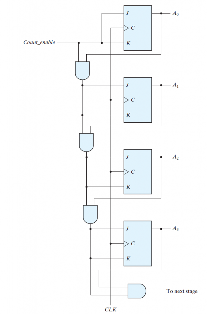
As given in diagram that we make a binary counter by using jk-flip-flop in which when both inputs are one then it toggle output .So for binary counter I give the first jk-flip flop direct count and to other of them I give the output of all the flip flop which comes before it so if the output of any flip flop except the last one is one and the count is enable then it got toggle and in the last carryout when all the flip-flops output are one so in this a simply binary counter works now here we understand the working of parallel load circuit its diagram is given below
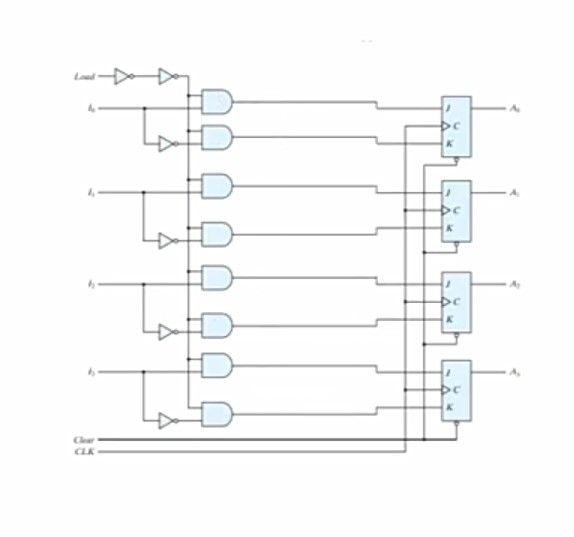
As given in the above diagram that we apply load at the one of the inputs of all the circuit gates and we connect the second inputs of the gate with our actual input in such a way that a normal input if is applied on one gate then its complement is applied on the gate whose output is going to the same flip-flop with which it is connect in simply we apply the input on the circuit in such a way that complement of j input of flip-flop is applied on k input of flip-flop .So as a result of it whenever the load is enable the applied input is carried to the resistor circuit.
Now we make the binary counter with parallel load for this purpose we sum up both the binary counter circuit and the parallel load circuit then it look like that as given below
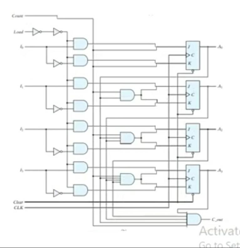
Here is problem that when both load and count are enable the purpose of making circuits loses therefore we simply connect the count and the NOT of load with AND gate and we added OR gates before each input of resistor circuit then the resulted circuit look like that
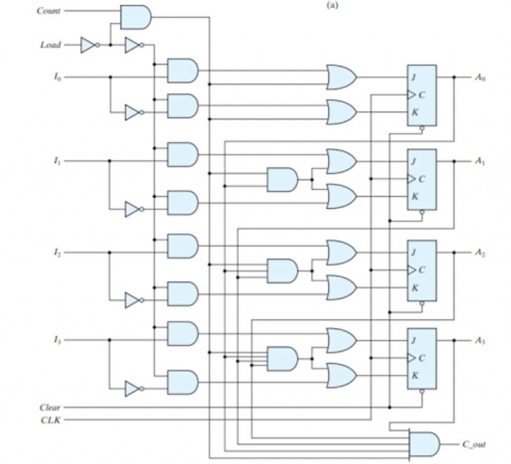
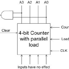
Now this is the binary counter circuit with parallel load. Let’s explore it’s working. As we know that in a circuit we enable only one out of both load and count at time. Therefore, when load is enable then all the and gate passes the value of load to the resistor circuit. Similarly, when count is enable then circuit passes the value of count to resistor circuit and when both of them have zero value then jk flip-flop work as memory state. So in this way the binary counter with parallel load works. Now here if we look the generic view of this circuit. Then its block diagram is given below
Here if we look at the table of the given circuit in the form of clear, clock, load, and count then the function of given circuit look like that
| Clear | CLK | load | Count | Function |
| 0 | X | X | X | Clear to 0 |
| 1 |
↑
|
1 | X | Load inputs |
| 1 | ↑
|
0 | 1 | Count next binary state |
| 1 | ↑
|
0 | 0 | No change |
Now if we look in the table then we come to know that when clear is zero the all means clock load count fall in condition of don’t care then the function output also becomes clear to zero. The next important term in the table is load when its value is one then the flip-flop takes the value of all the parallel loads instead taking count value. Similarly, when count has a value of one the flip-flop circuit moves to next binary start. In the last when both of them has zero value then no change occur at the output.
Also read the relevant topics
https://eevibes.com/digital-logic-design/discuss-the-flip-flops-and-registers-in-digital-design/