How to convert Jk flip-flop into D-flipflop?
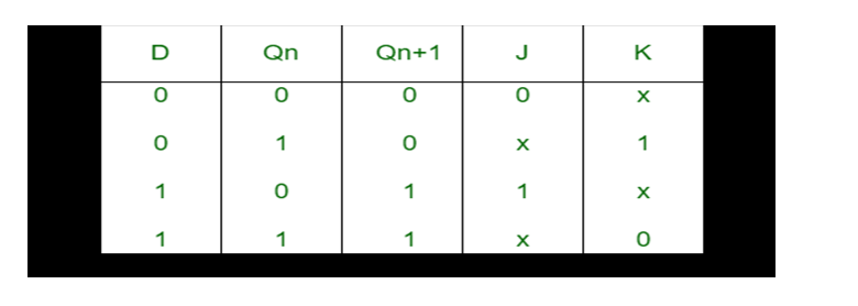
How to convert Jk flip-flop into D-flipflop? We construct the characteristic table of D flip-flop and excitation table of JK flip-flop. In case of converting JK flip flop into D flip flop, D is the external input of the combinational circuit, whereas J and K are the inputs of the actual flip flop.
D and Qn make four combinations. So, prepare a conversion table and using this table express J and K in terms of D and Qn. The conversion table, K-map and logic diagram for the conversion of JK flip flop to D flip flop is shown below:
Step-2:
Using the K-map we find the boolean expression of J and K in terms of D.
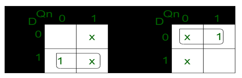
J=D
K=D
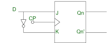
Step-3:
We construct the circuit diagram of the conversion of JK flip-flop into D flip-flop.
Give an application of SR latch?
Digital systems use switches to input values and to control the output. For example, a keypad uses 10 switches to enter decimal numbers 0 to 9. When a switch is closed the switch contacts physically vibrate or ‘bounce’ before making a solid contact. The switch bounce causes the voltage at the output of the switch to vary between logic low and high for a very short duration before it settles to a steady state. The variation in the voltage causes the digital circuit to operate in an erratic manner.
An S-R latch connected between the switch and the digital circuit prevents the varying switch output from reaching the digital circuit. when the switch is moved up to connect the resistor to the ground, the output voltage fluctuates between logic 1 and 0 for a very brief period of time when the switch vibrates before making a solid contact.
The output voltage settles to logic 0 when a solid contact is made. The active-low input S-R latch. prevents the output signal from varying between logic 1 and 0. When the switch is moved from down position to up position, the R input is set to 1 and S input is set to 0, which sets the Q output of the S-R latch to 1. The S input varies between 0 and 1 due to switch ‘bounce’, however the S-R latch doesn’t change its output state Q when S = 1 and R = 1.
Also read here
https://eevibes.com/digital-logic-design/how-to-draw-state-diagram-of-sequential-circuit/