
What is the difference between fan-in and fan-out?
In this article you will learn about what is the difference between fan-in and fan-out with examples? Fan-in and Fan-out are characteristics of Digital ICs. Digital ICs are complete functioning logic networks. Typically, a Digital IC requires only a power supply, I/P (input) and O/P (output). Here are the definitions of Fan In and Fan Out.
What is Fan-In?
Fan-in refers to the maximum number of input signals that feed the input equations of a logic cell. Fan-in is a term that defines the maximum number of digital inputs that a single logic gate can accept. Most transistor-transistor logic ( TTL ) gates have one or two inputs, although some have more than two. A typical logic gate has a fan-in of 1 or 2.
In some digital systems, it is necessary for a single TTL logic gate to drive several devices with fan-in numbers greater than 1. If the total number of inputs a transistor-transistor logic (TTL) device must drive is greater than 10, a device called a buffer can be used between the TTL gate output and the inputs of the devices it must drive. A logical inverter (also called a NOT gate) can serve this function in most digital circuits.
In quantum logic gates the fan-in always has to be equal to the number of outputs, the Fan-out. Gates for which the numbers of inputs and outputs differ would not be reversible (unitary) and are therefore not allowed.
In the fan-in always has to be equal to the number of outputs, the fan in. Gates for which the numbers of inputs and outputs differ would not be reversible and are therefore not allowed.
How to Design a 4 bit Magnitude Comparator Circuit? Explanation with examples
what is fan-out?
The fan-out is defined as the maximum number of inputs (load) that can be connected to the output of a gate without degrading the normal operation. Fan Out is calculated from the amount of current available in the output of a gate and the amount of current needed in each input of the connecting gate. It is specified by manufacturer and is provided in the data sheet. Exceeding the specified maximum load may cause a malfunction because the circuit will not be able supply the demanded power.
More complex analysis than fan-in and fan-out is required when specific good judgment families are interconnected. Fan-out is in the long run determined by the maximum supply and sink currents of an output and the maximum supply and sink currents of the connected inputs; the riding tool must be able to supply or sink at its output the sum of the currents needed or supplied (depending on whether the output is a good judgment excessive or low voltage degree) by all of the linked inputs, whilst maintaining the output voltage specifications. For every good judgment family, usually a “general” enter is defined by the producer with maximum input currents at each logic degree, and the fan-out for an output is computed as the number of those popular inputs that may be driven inside the worst case.
Also see: How to Create a Test Bench for Verilog HDL Module?
Also see: What are the Practical Aspects of Digital Circuit Design?
High fan-in NMOS NAND Gate
Consider the following figure in which k-inputs are present at the input of NMOS NAND gate. Let us say that we are interested in calculating the effect of these multiple inputs on the propagation delay tP. These k NMOS transistors have same length L and width K. Since they all are connected in series so we can consider them as a single transistor with k ×L length and W width. The the formula for propagation delay is:
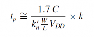
where C= equivalent capacitance contributed by the k transistors. If the width is increased, then the performance is also improved. But this will result in increased C and chip area.
Also check:
How to design a four bit adder-subtractor circuit?
High fan-in CMOS logic gates are not practically used as they require either k PMOS or NMOS transistors connected in series. Two or more lower fan-in gates are used for designing high fan-in CMOS logic gates. Let’s say if you want to design 6-input AND gate, use 2 3-input AND gates that connect to 2-input AND gate.
Inverter that drives n other inverters
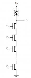
Consider the following figure in which an inverter N1 drives the inputs of n other inverters. Every inverter will contribute to the total capacitance at the junction point f. These n inverters can be represented by one large capacitor Cn. So the capacitance contributed by n inverters is given as:
Cn=C×n

DC Fan out:
A perfect logic gate would have infinite input impedance and zero output impedance, allowing a gate output to drive any number of gate inputs.
EXPLANATION: The fan-out is the number of inputs that can be connected to an output before the current required by the inputs exceeds the current that can be delivered by the output.
AC fan-out:
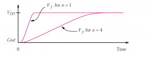
However, inputs of real gates have capacitance as well as resistance to the power supply rails. This capacitance will slow the output transition of the previous gate and hence increase its propagation delay. As a result, rather than a fixed fan-out the designer is faced with a trade off between fan-out and propagation delay.
Fan-in and Fan-out Effects:
- In the LOW state the output voltage VOLmay increase above VOLmax.
- In the HIGH state the output voltage VOHmay decrease below VOHmin.
- The operating temperature of the device may increase, thereby reducing the reliability of the device and eventually causing the device to fail.
- Output rise and fall times may increase beyond specifications.
What are some applications of fan out and fan in in electrical engineering?
Fan out is used when we need to connect two devices together, like when you plug an electric cord into a wall and a battery into the other side.
Fan in is also used when we need to connect two devices together, but we don’t have any electricity.
What is the unit load? Give an example
Fan out is specified in terms of unit loads. A unit load for a logic gate equals one input to a like circuit.
Also see: How to add User Defined Primitives in Xilinx Verilog HDL Programming?
What are the limits on fan out of a gate?
If more gate inputs than specified fan out of gate are connected then the gate may not work properly. Even without exceeding the fan out of a gate, each additional input causes the loading effect on gate thus resulting in increased switching time.
These limitations are actually caused by the current flow when input is supposed to be held at one level usually 0. So there is a limit on fan out as more gate driven will require more current. Fan out the important specification of digital ICs.
Conclusion
Fan out and fan in are so important in electrical engineering because they allow us to create and control the flows of energy in our systems. By understanding how they work and how to use them safely, we can create reliable, efficient and safe electrical systems.
Related Topics
- What are the CMOS Logic Gates?
- How to design a 4 bit magnitude comparator circuit? Explanation with examples
- What is the magnitude comparator circuit? Design a 3 bit magnitude comparator circuit
- What are the synchronous counters? Explain with an example.
- How to design a 4 bit magnitude comparator circuit?
- what are the half adder and full adder circuits?
- what are the half subtractor and full subtractor circuits?
- How to design a four bit adder-subtractor circuit?
- What are number systems in computer?
- Discuss the binary counter with parallel load? Explain its working with an example
- how to draw state diagram of sequential circuit?
- How to simplify a Boolean function using Karnaugh map (k-map)?
- What are the flip flops and registers in digital design?
- Define fan-in, fan-out, CMOS and TTL logic levels
- what is the Canonical form representation of Boolean function?
- What is difference between latches and flip flops?