what are the BCD and binary ripple counters?
what are the BCD and binary ripple counters? BCD or decade counter circuit. a binary coded decimal is a serial digital counter that counts 10 digits. Whenever the new clock input was given, it is reset. As it is can be worked under ten different unique combinations of output so it is also known as “Decade counter”.
A binary coded decimal counter basically consists of four clock D-type flip-flops connected as a counter. They can count up from zero to 9 or down from 9 to zero. The output is shown in the binary form always.
How does BCD counter work?
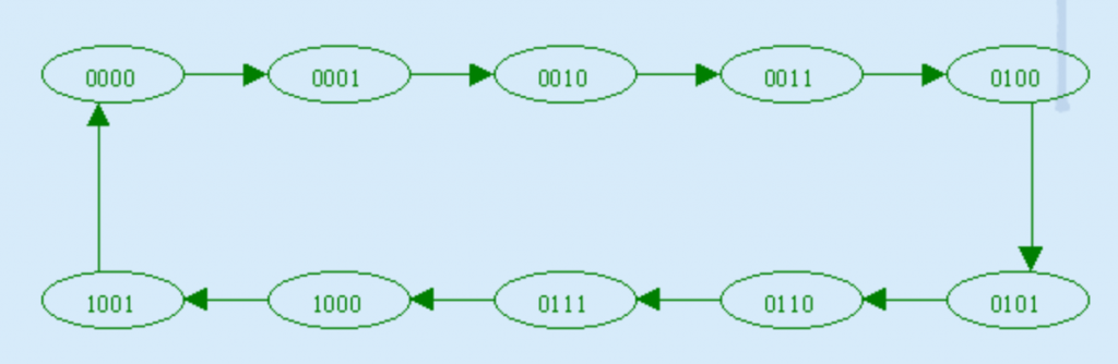
BCD counters follow a sequence of 10 states and they count them by using bcd numbers which are from 000 0 to 1001 and then returns to 0000 and repeats it. search a counter always have at least 4 flip flops which represent each decimal digit, as always a decimal digit is represented by our binary code with at least 4 bits giving a Mod-10 count.
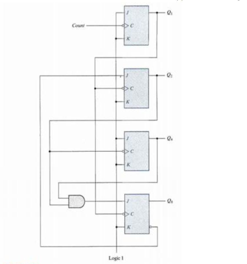
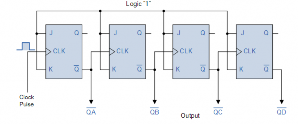
The logic diagram of a BCD ripple counter using JK flip-flops is shown in the below figure. The four outputs are designed by the letter symbol Q with a numeric subscript equal to the binary weight of the corresponding bit in the BCD code. Note that the output of Q1 is applied to the C inputs of both Q2 is applied to the C input of Q4. The J and K inputs are connected either to a permanent 1 signal or to outputs of other flip-flops.
The operation of the counter can be explained by a list of conditions for flip-flop transitions. These conditions are derived from the logic diagram and from the knowledge of how JK flip-flop transitions. These conditions are derived from the logic diagram and from knowledge of how JK flip-flop operates.
The operation of the counter can be explained by a list of conditions for flip-flop transitions. These conditions are derived from the logic diagram and from the knowledge of how JK flip-flop transitions. These conditions are derived from the logic diagram and from knowledge of how JK flip-flop operates.
For the verification of these conditions result the sequence required by the BCD ripple counter, it is necessary to verify that the flip-flop transitions indeed follow a sequence of states as specified by the state diagram of above shown.
The ten BCD or counter circuit is designed using JK flip flops and the NAND gate. The BCD calculator design is very simple, and requires 4 JK flip flops because it is a 4-bit binary counter. The design of the ten counter is shown below
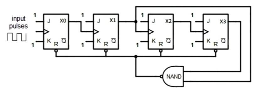
From this figure, we see that the effects of J and K are connected to logic 1. Input or clock inputs per flop are inserted as output to the next flip flop, but not the last flip flop. CLR input includes NAND gate output similarly to reset all flip flops when the number is reached.
The BCD or ten counter has 4 jk flip flops with 16 junctions as shown in the figure above. Of the 16 regions, ten were used. When counters are connected to a series, we can count up to 100 or 1000 based on an app. The name Modulus is not a complete calculation that the counter has the ability to calculate pulses. When the calculator calculates the calculation, it reaches zero, called the modulus n-counter. Examples include this mod-8 counter, mod-16 counter, etc. The calculation distance of the n-bit modulus counter ranges from 0 to 2n-1. Similarly, a BCD counter is a Mod-10 counter, which returns to zero after counting from 0 (0000) to 9 (1001), representing the result in the decimal form. (that means dividing by 10 count). Therefore, it is called a binary coded decimal counter (BCD Counter). It is code 8421 (binary 4-digit or bits), which contains 4-digit binary and is very easy to make binary and decimal conversions. The ten counter is a simple 4-bit binary counter with 4 effects – QA, QB, QC, QD. When the number has reached count to 10, then reset all flip-flops by subtracting binary 0 (0000) each time and start the counting cycle again. The reset pins of R1, R2, R3, and R4 are used to reset and reset IC 7490.
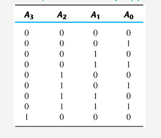
When the reset pins are R1, R2 is high and R3, R4 are set, output QA, QB, QC, QD is set to 0 (0000) and reset counter. When R3, R4 is high, the result is set to 9 (1001). The counter power of the counter 74LS90 ten can be increased by connecting over the ICs in the series. It saves and represents the result in the decimal form as shown in the fact table above.
Applications for BCD Counters or Decade Counters
An electronic circuit with a clock signal is known as the ten counter. It is a 4-bit binary input region. The use of a BCD counter or ten counter is as follows
- Clock circuits
- Divorce frequency
- Calculation cycles are common
- Government equipment
- Consecutive
- Clock separation
- Low CMOS power circuits
- Oscillators are integrated
- Clock production
- TTL compatible inputs etc. Used
BINARY RIPPLE COUNTER
A Binary counter is a 2-Mod counter that counts up to 2-bit state values, i.e., 22 = 4 values. Flip flops with the same flexibility as T and JK are used to build the Ripple counter. Below is a regional diagram of the ripple counter. In the regional design of the ripple counter counter, two JK flip flops are used. The high-power signal is transmitted to the input of both flip flops. This high power installation keeps flip flops in 1 position. In JK flip flops, misuse caused by the use of the clock.
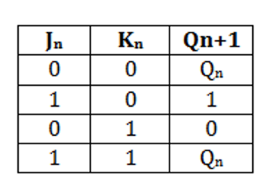
The results for Q0 and Q1 are LSB and MSB bits, respectively. The true JK flip flop table helps us understand the functionality of the counter. When the voltage is high in the input of flip flops, the fourth condition of the JK flip flop occurs. Flip flops will be in state 1 when we use high power in flip-flop installation.
Therefore, the ground circuits of the flip flops are shifted to the negative end of the clock. In simple terms, the flip flop rotates when the clock shift occurs from 1 to 0. The Q0 release status changes when the negative edge of the clock passes to the flip flop. Initially, all flip flops are set to 0. These flip flops change their position when the clock goes from 1 to 0. from 0 to 1. In all clocks, the process remains the same. To understand the operation of the 4-bit binary ripple counter.
The count start with binary 0 an agreements by 1 with each count pulse input after the count of 15, the counter goes back to zero for the reputation of the account. the least significant bit a is complemented with 1 to 0 it compliments A2. Every time that a two goes from 1 to 0, it compliments A3 and the cycles continue like this.
A binary counter with a reverse count it’s called a binary countdown counter. In a downward counter, the binary count is decremented by 1 with every input pulse. The count of a four-bit countdown counter starts from binary 15 and continues to binary counts 14, 13, 12 coma…, 0 and then back to 15.
related topics
- what are the half adder and full adder circuits?
- what are the half subtractor and full subtractor circuits?
- How to design a four bit adder-subtractor circuit?
- What are number systems in computer?
- Discuss the binary counter with parallel load? Explain its working with an example
- how to draw state diagram of sequential circuit?
- How to simplify a Boolean function using Karnaugh map (k-map)?
- What are the flip flops and registers in digital design?
- Define fan-in, fan-out, CMOS and TTL logic levels
- what is the Canonical form representation of Boolean function?
- What is difference between latches and flip flops?