Table of Contents
What is a parity bit?
What is a parity bit? How to design a Parity bit checker and generator? The parity generating technique is one of the most widely used error detection techniques for the data transmission. In digital systems, when binary data is transmitted and processed , data may be subjected to noise so that such noise can alter 0s (of data bits) to 1s and 1s to 0s.Hence, parity bit is added to the word containing data in order to make number of 1s either even or odd. The most common error detection code used is the parity bit.
A parity bit is an extra bit included with a binary message to make the total number of 1’s either odd or even. In case of even parity, the parity bit is chosen so that the total number of 1’sin the coded message is even. Alternatively, odd parity can be used in which the total number of 1’s in the coded message is made odd. During transfer of information, the message at the sending-end is applied to a parity generator where the parity pit is generated. At the receiving-end a parity checker is used to detect single bit error in the transmitted data word by regenerate the parity bit in the same fashion as the generator.
What is Parity bit Generator?
A parity generator is a combinational logic circuit that generates the party bit in the transmitter. On the other hand circuit that checks the parity in the receiver is called parity checker. A combined circuit or devices of parity generator and parity checkers are commonly used in digital systems to detect the single bit errors in the transmitted data word The sum of the data bits and parity bits can be even or odd. In even parity, the added parity bit will make the number of 1s an even amount whereas in odd parity the added parity bit will make the total number of 1s an even amount.
It is combinational circuit that accepts an n-1 bit stream data and generates the additional bit that is to be transmitted with the bit stream. This additional or extra bit is termed as a parity bit.
In even parity bit scheme, the parity bit is 0 if there are even number of 1s in the data stream and the parity bit is 1 if there are odd number of 1s in the data stream. In odd parity bit scheme the parity bit is 1 if there are even number of 1s in the data stream and the parity bit is 0 if there are odd number of 1s in the data stream.
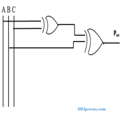
Even Parity Generator
Let us assume that a 3-bit message is to be transmitted with an even parity bit. Let the three inputs A, B and C are applied to the circuits and output bit is the parity bit P. The total number of 1s must be even to generate the parity be P.
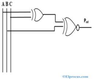
Odd Parity Generator
Let us consider that the 3-bit data is to be transmitted with an odd parity bit. The three inputs are A, B, C and P is the output parity bit. The total number of bits must be odd in order to generate the odd parity bit.
What is Parity bit Checker?
It is a logic circuit that checks for possible errors in the transmission. This circuit can be an even parity checker or parity checker depending on the type of parity generated at the transmission end. When this circuit is used as parity checker, the number of input bits must always be even. When a parity error occurs, the ‘sum even’ output slow and ‘sum odd’ output goes high. If this logic circuit is used as an odd parity checker, the number of input bits should be odd, but if an error occurs the ‘sum odd’ output goes low and ‘sum even’ output goes high.
Even Parity Checker
Consider that three input message along with even parity bit is generated at the transmitting end. These 4 bits applied as input to the parity checker circuit which checks the possibility of error on the data. Since the data transmitted with even parity, four bits received at circuit must have an even number of 1s If any error occurs, the received message consists of odd number of 1s. The output of the parity checker is denoted by PEC (parity error check).
Odd Parity Checker
Consider that a three-bit message along with odd parity bit is transmitted at the transmitting end. Odd parity checker circuit receives these 4 bits and checks whether any error are present in the data If the total number of is in the data is odd, then it indicates no error, whereas if the total number of 1s is even it indicates the error since the data is transmitted with odd parity at transmitting end
Parity Generator/Checker IC
There are different types of parity generator /checker ICs available with different input configurations such as 5-bit, 4-bit, -bit, 12-bit, etc. A most commonly used and standard type of parity generator/checker IC is 74180, It is a 9-bit parity generator or checker used to detect errors in high speed data transmission or data retrieval system. This IC can be used to generate a 9-bit odd or even parity code or it can be used to check for odd or even parity 9-bit code (5 data hits and one parity bit).
Designing of Parity Generators/Checkers
Exclusive-OR functions are very useful in systems requiring error detection and correction codes. Binary data, when transmitted and processed , is susceptible to noise that can alter its 1s to 0s and0s to 1s.To detect such errors, an additional bit called the parity bit is added to the data bits and the word containing the data bits and the parity bit is transmitted. At the receiving end the number of1s in the word received arc counted and the error if any error is detected. This parity check however detects only single bit errors.
The circuit that generates the parity bit in the transmitter is called a parity generator. The circuit that checks the parity in the receiver is called a parity checker. A parity bit a 0 or a 1 is attached to the data bits such that the total number of 1s in the word is even for even parity and odd for odd parity. The parity bit can be attached to the code group either at the beginning or at the end depending on system design, A given system operates with either even or odd parity but not both. So a word always contains either an even or an odd number of 1s.
At the receiving end if the word received has an even number of 1s in the odd parity system or an odd number of 1s in the even parity system.it implies that an error has occurred. In order to check or generate the proper parity bit in a given code word the basic principle used is “The modulo sum of an even number of 1s is always a 0 and the modulo sum of an odd number of 1s is always a 1”. Therefore in order to check for an error all the bits in the received word are added. If the modulo sum is a 0 for an odd parity system or a 1 for an even parity system an error is detected.
To generate an even parity bit the four data bits are added using three X-OR gates. The sum bit will be the parity bit. To generate an odd parity bit, the four data bits are added using three X-OR gates and the sum bit is inverted. This device can be used to check for odd or even parity in a 9-hit code (8 data bits and one parity bit), or it can be used to generate a 9-bit odd or even parity code.
As an example, consider a three-bit message to be transmitted with an odd-parity bit. Table 4-4 shows the truth table for the parity generator. The three bits x, y, and z constitute the message and are the inputs to the circuit. The parity bit P is the output. For odd parity, the bit P is generated so as to make the total number of 1’s odd (including P). From the truth table P = 1 when the number of 1’s in x, y, and z is even. so the function for P can be expressed as follows:
P = x (X-OR) y (X-NOR) z
The logic diagram for the parity generator consists of one two-input exclusive-OR gate and one two-input equivalence gate. The two gates can be interchanged and still produce the same function, since P is also equal to:
P = x (X-NOR) y (X-OR) z
The three-bit message and the parity bit are transmitted to their destination where they are applied to a parity-checker circuit. An error occurs during trans-mission if the parity of the four bits received is even, since the binary information transmitted was originally odd. The output C of the parity checker should be a 1 when an error occurs, i.e., when the number of 1’s in the four inputs is even. From the truth table it can be seen that the function for C consists of the eight min terms with numerical values having an even number of 0’s. so the function can be expressed with equivalence operator as follows:
C=x(X-NOR)y(X-NOR)z(X-NOR)P
Three-bit message Parity bit generated
x y z P
0 0 0 1
0 0 1 0
0 1 0 0
0 1 1 1
1 0 0 0
1 0 1 1
1 1 0 1
1 1 1 0
Similarly the even parity expression implemented by using two Ex-OR gates and the logic diagram of this even parity using the Ex-OR logic gate is shown below.
Also read here
https://eevibes.com/digital-logic-design/what-are-the-bcd-and-binary-ripple-counters/