Table of Contents
What are the Counters?
What are the synchronous and asynchronous counters? Counter circuits are employed in digital systems for a variety of applications. Counters may be used to count the number of occurrences of specified events in a system, generate timing intervals for control of various tasks in a system, maintain track of the amount of time that has elapsed between specific events, and perform other functions.
Counters can be designed utilizing the adder/subtractor circuits as well as the registers. Nevertheless, because we just need to update the contents of a counter by one, it is not required to employ such complex circuits. Instead, we can employ circuits that are far simpler and have a significantly cheaper price tag. In this article, will demonstrate how T and D flip-flops can be used to create counter circuits.
Asynchronous Counters
Because the toggle feature is inherently suited for the implementation of the counting operation, the simplest counter circuits can be made utilizing T flip-flops.
Up-Counter using T Flip-Flops
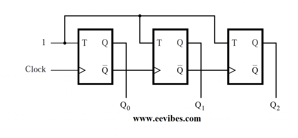
A three-bit counter capable of counting from 0 to 7 is shown in Figure below. The three flip-flops’ clock inputs are linked in a cascade. Each flip-T flop’s input is linked to a constant 1, indicating that the flip-state flop’s will be reversed (toggled) on each positive edge of its clock. The aim of this circuit, we assume, is to count the number of pulses that occur on the primary input, Clock. The first flip-clock flop’s input is thus connected to the Clock line. The clock inputs of the other two flip-flops are driven by the Q output of the previous flip-flop. As a result, anytime the previous flip-flop changes its state from Q = 1 to Q = 0, resulting in a positive edge of the Q signal, they toggle their state.
The counter’s timing diagram is shown in Figure below. Each clock cycle, the value of Q0 changes. The transition occurs immediately after the Clock signal’s positive edge. The propagation delay through the flip-flop causes the delay. The value of Q1 changes quickly after the negative edge of the Q0 signal, because the second flip-flop is clocked by Q0.
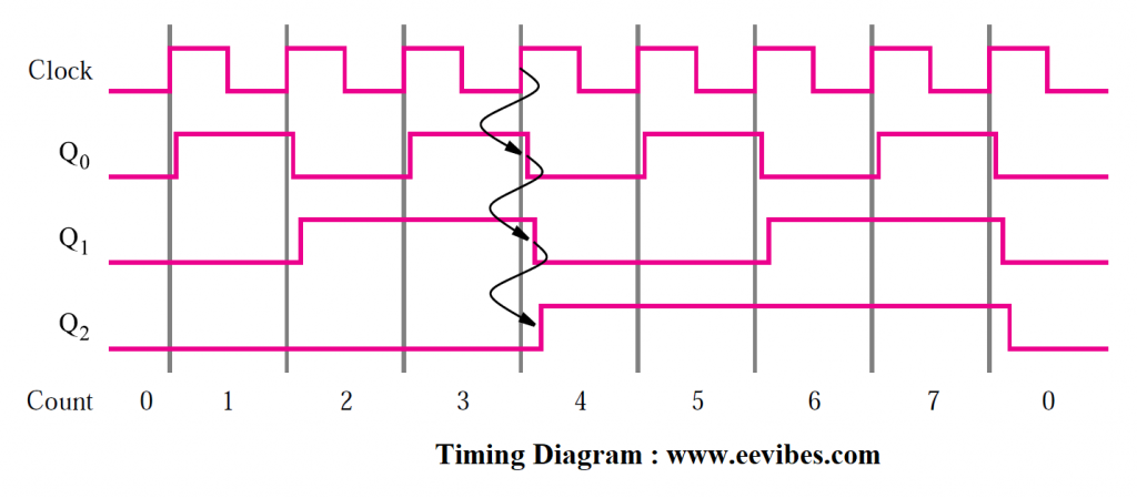
Similarly, just after the negative edge of the Q1 signal, the value of Q2 changes. If we use the values Q2Q1Q0 as the count, the counting sequence is 0, 1, 2, 3, 4, 5, 6, 7, 0, 1, and so on. This is a modulo-8 counter circuit. We call it an up-counter since it counts in the upward direction.
Figure (a) shows a counter with three phases, each with a single flip-flop. Only the first stage is synced to the clock because it responds immediately to the Clock signal. After an additional wait, the other two phases respond. When Count = 3, for example, the following clock pulse will cause the Count to increase to 4. This modification necessitates the toggling of the states of all three flip-flops, as represented by the arrows in Figure b’s timing diagram. After a propagation delay from Clock’s positive edge, the change in Q0 is seen. Because the Q1 and Q2 flip-flops have not yet changed, the count is Q2Q1Q0 = 010 for a short period. After a second propagation delay, the change in Q1 emerges, and the count is 000. After a third delay, the shift in Q2 occurs, indicating that the circuit has entered its stable condition and the count has reached 100. This is analogous to the rippling of carries in Figure 5.6’s ripple-carry adder circuit. Figure (a) shows an asynchronous counter, sometimes known as a ripple counter.
Down-Counter with T Flip-Flops
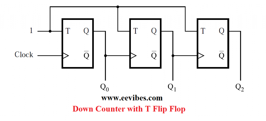
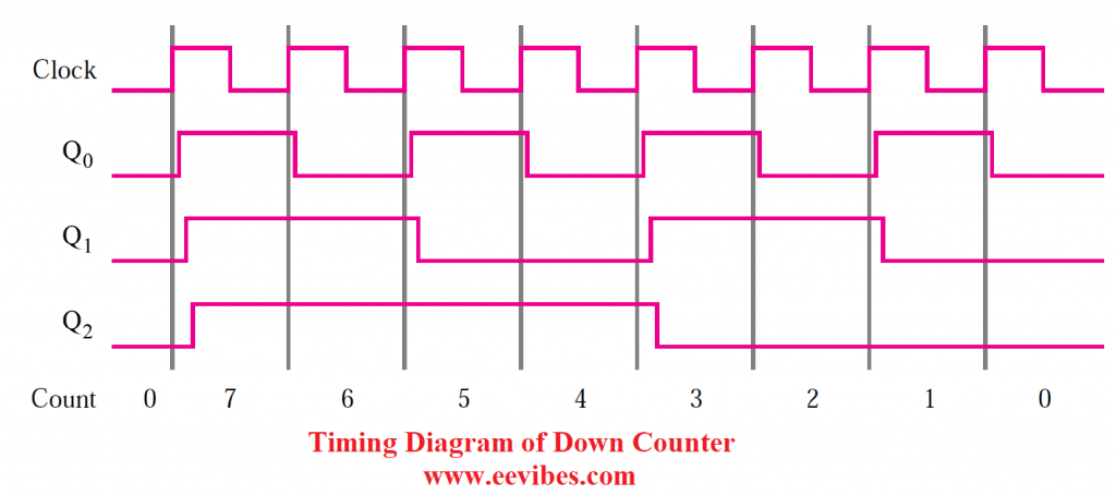
Figure (c) shows a small modification of the circuit in Figure (a). The sole change is that the clock inputs of the second and third flip-flops in Figure (c) are driven by the preceding stages’ Q outputs rather than the Q outputs. This circuit counts in the sequence 0, 7, 6, 5, 4, 3, 2, 1, 0, 7, and so on, according to the timing diagram in Figure (d). We call it a down-counter since it counts in the downward direction.
The functionality of the circuits in Figures (a) and (c) can be combined to create a counter that can count up or down. An up/down counter is one such counter.
Also read here
- how to draw state diagram of sequential circuit?
- What is the magnitude comparator circuit? Design a 3 bit magnitude comparator circuit
- How to design a four bit adder-subtractor circuit?
- How to design a 4 bit magnitude comparator circuit?
- What is the difference between fan-in and fan-out?
- How to perform Packed BCD to ASCII conversion?
- What are the decoders? how are they different from encoders?
- How to implement Boolean functions using multiplexer?