
Implementation of Functions using Multiplexer
Implementation of Boolean function using multiplexer (MUX) is very simple. If you want to implement a Boolean function of n variables, you need a multiplexers that has (n-1) select lines. The purpose of select lines in a multiplexer is to choose which input to be forwarded to output lines. For
2n input lines, you will always have n select lines and a single output line.
Procedure of Functions Implementation using MUX
In order to implement a Boolean function using mux follow the following procedure:
Use the first (n-1) variables of functions as select lines of multiplexer
. The remaining variable of function is used as data line or data input. For example if you want to implement a 3 variable function
F(A,B,C)
then A and B will be used as select lines
C can take four possible values (C or C’ or 1 or 0). This variable will be used as data input to the MUX.
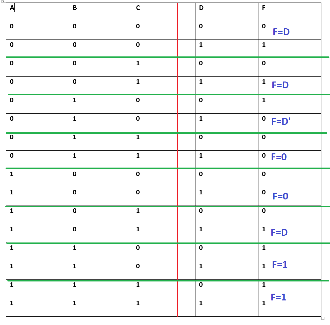
Example
Implement the following Boolean function using MUX.
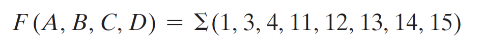
Solution:
First make the truth table as shown below
Select n-1 variables for select lines of MUX (ABC). This will help us to decide to use 8 to 1 line MUX.
Use the last variable (D) for representing it in terms of function as shown in the table
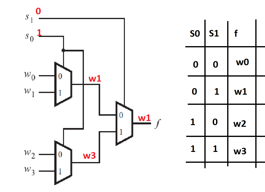
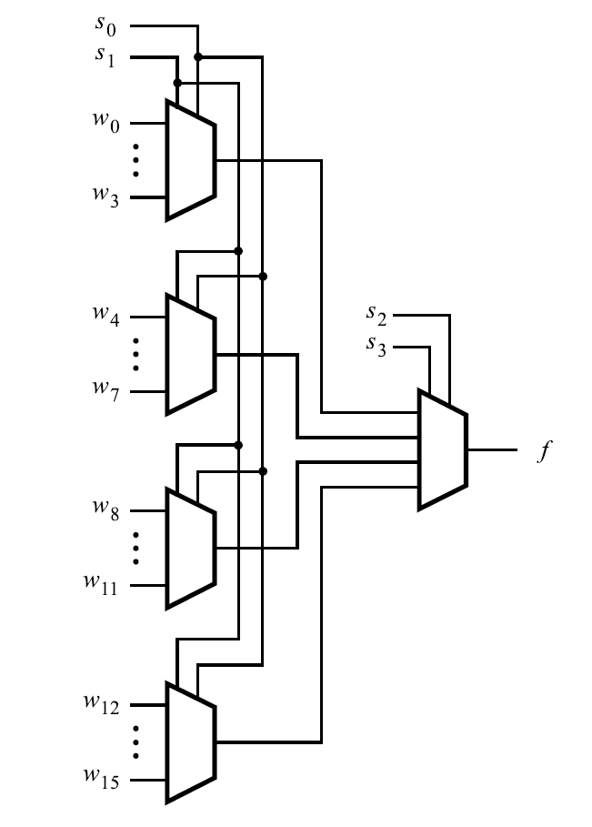
How to design a 4 to 1 line MUX using 2 to 1 line MUX?
The above figure shows the design of 4 to 1 line MUX using 2 to 1 line MUX. The working of this circuit is explained as follows. When 01 is selected, w1 should be forwarded to the output line.
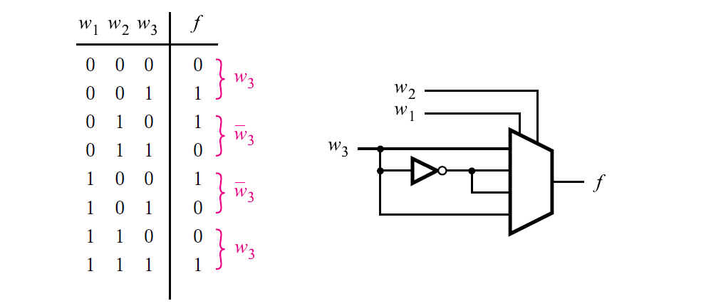
How to design a 3-input majority function using mux?
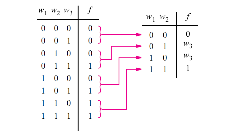
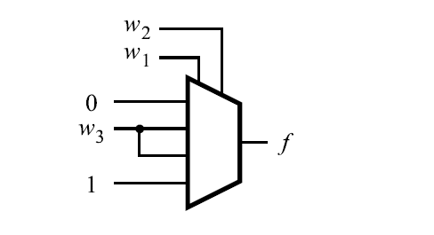
using a 4-to-1 multiplexer.
(a)
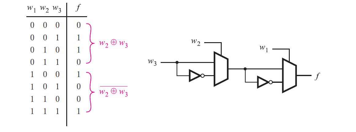
How to design a 3 input XOR gate using MUX?
4.32 Implement the following Boolean function with a multiplexer (a)
F(A, B, C, D) =Σ(0, 2, 5, 8, 10, 14)
(b) F(A, B, C, D) =∏(2,6,11)
Solution (a):
Solution (b):
Also read here
What are the universal shift registers and their applications?