Multiplexers
What are the multiplexer circuits? Multiplexer is device that selects between many input signal or analog and transfer these inputs into single output line. Multiplexer also shorten to MUX or MPX. Multiplexer is also called data selector because it selects analogs inputs and transfers it into single output. These selection is separated by digital signals also known as select lines.
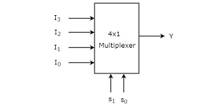
A multiplexer has 2^n input lines, n select lines and always a single output line. Select inputs decide which input should be forwarded to the output line.
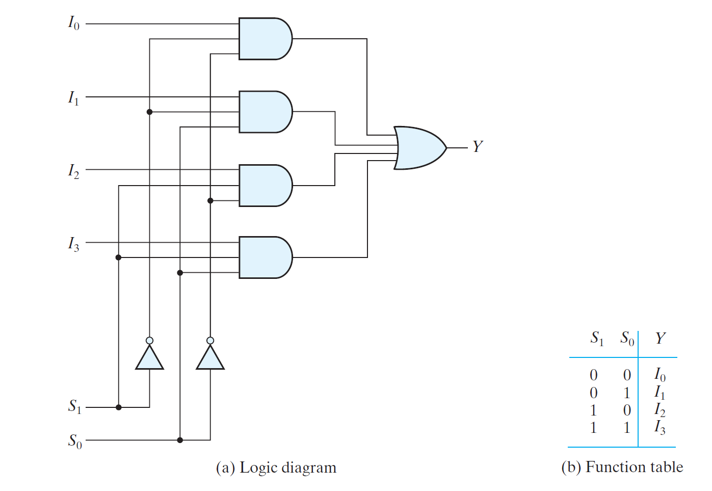
A 4-1-line multiplexer as shown in figure above each has four input lines I0 to I3, is applied to one input of an AND gate. Selection lines s1 and s0 are decoded to select an AND gate. The function table lists the input to output path for each particular bit combination of selection lines.
To demonstrate the circuit operation, consider case s1s0= 10 tie AND gate which associates with input 12 has two of its input equals to 1 and the third input connected to i2. The other 3 AND gates have at least one input equals to 0. The OR gate output is now equal to value I2, thus providing path from selected inputs to output. The outputs of and gate are applied to a single OR gate to provide 1-line output. The size of multiplexer is specified by 2^n of its output lines and single output lines.
Boolean Functions Implementation using MUX
It was displayed in the past area that a decoder can be utilized to execute a Boolean work by utilizing an outside OR door. A speedy reference to the multiplexer of uncovers that it is basically a decoder with the OR entryway currently accessible. The minterms out of the decoder to be picked can be controlled with the information lines. The midterms to be incorporated with the capacity being carried out are picked by making their comparing input lines equivalent to I; those minterms excluded from the capacity are incapacitated by making their feedback lines equivalent to 0. This gives a technique for carrying out any Boolean capacity of n factors with a 2″- to-1 multiplexer. Nonetheless, it is possible to show improvement over that. On the off chance that we have a Boolean capacity of n + 1 factors, we take n of these factors and interface them to the determination lines of a multiplexer. The leftover single variable of the capacity is utilized for the contributions of the multiplexer. In case An is this single variable, the in- puts of the multiplexer are picked to be either An or A’ or 1 or 0. By reasonable utilization of these four qualities for the information sources and by interfacing different factors to the determination lines, one can carry out any Boolean capacity with a multiplexer. It is conceivable to create any capacity of m + 1 factors with a 2″- to-1 multiplexer. To show this method with a substantial model, consider the capacity of three factors:
F (A, B. C) = Y(1, 3, 5, 6)

The capacity can be executed with a 4-to-1 multiplexer,Two of the factors, B and C, are applied to the choice lines in a specific order, i.e., B is associated with s, and C to so. The contributions of the multiplexer are 0, 1, A, and A’. When BC = 00, yield F = 0 since/= 0. Accordingly, both minterms mo = A’B’C’ and m. = AB’C’ produce a 0 yield, since the yield is 0 when BC = 00 paying little heed to the worth of A. At the point when BC = O1, yield F = I. since/= 1. Thusly, both minterms m, = A’B’C and m. = AB’C produce a 1 yield, since the yield is 1 when BC = 01 notwithstanding the worth of A. At the point when BC = 10, input 1: is chosen. Since An is associated to this information, the yield will be equivalent to 1 just for minterm m. = ABC be that as it may, not for minterm my = A’ BC , on the grounds that when A = 1, then, at that point, A = 0, and since 1- = 0. we have F = 0. At last, when BC = 11, input/, is chosen. Since A’ is associated with this in- put, the yield will be equivalent to I just for minterm », = A’BC. yet, not for ». = ABC.
Uses of Multiplexers
A Multiplexer is utilized in various applications like, where numerous information can be communicated utilizing a solitary line.
Correspondence System
A Multiplexer is utilized to build the effectiveness of the correspondence framework by permitting the transmission of information like sound and video information from various stations by means of links and single lines.
PC Memory
A Multiplexer is utilized in PC memory to keep up a huge measure of memory in the PCs, and furthermore to diminish the quantity of copper lines important to associate the memory to different pieces of the PC.
Phone Network
A multiplexer is utilized in phone organizations to incorporate the different sound signs on a solitary line of transmission.
Transmission from the Computer System of a Satellite:
A Multiplexer is utilized to send the information signals from the PC arrangement of a satellite to the ground framework by utilizing a GSM correspondence.
Summary
They are basically used to reduce the number of logic gates that are require in a circuit they are also use for signal data line or when to carry two or more digital signals. The selection of each inputs is controlled by additional set of input called control lines. The signals either high or low is directly connected to the output of signals. Multiplexer is used for our convenient and it also help us in pc memory to keep up in measure of memory.
Also read here
What are the universal shift registers and their applications?