
Introduction
In this article you will learn about the Implementation of Dipole Antenna using CST Microwave Studio. Here, we have describes a simple Dipole Antenna that has been proposed and reviewed for wireless applications using a resonating frequency of 2.4 GHz, which is used by the majority of wireless devices. This design was completed successfully with the help of a simulation tool called CST Microwave Studio.
Learning Outcomes
- Introduction to CST Microwave Software.
- Analysis and Designing.
- Working of Dipole in Wireless Systems.
Introduction to Antenna
Antennas play a crucial role in wireless communication systems. Microwave and radio frequency have a direct impact on antennas, which then transfer signals via electro-magnetite waves into outer space. The weight and size of communication equipment have been drastically reduced thanks to advancements in mobile phone technology in order to develop antenna in the 2.4GHz band for the cellular network. Microstrip dipole antennas consist of a solid metal ground plane and a thin layer of reduced insulating material known as the dielectric substrate.
On the opposite side, where the antenna circuit is printed, there is partial metallization. Planar dipole-type in particular demonstrates a number of appealing characteristics, including a straightforward structure, low cost, low profile, and comfort on both planar and non-planar surfaces. As a result, it functions best in mobile and air applications. Because they essentially possess significant features including straightforward manufacture and analysis, as well as an alluring radiation pattern with low between-polarized rays, micro-strip dipole moments are appealing.
Design Parameters of an Antenna
Based on the resonance frequency, the dimensions of an antenna can fluctuate. A resonance frequency of 2.4 GHz was selected. These formulas are used to determine various antenna dimensions:
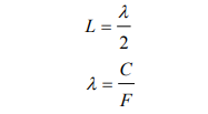
where λ denotes the wavelength, L denotes dipole’s length, F is the operating frequency, and C denotes the speed of light in space.
Frequency of Dipole Antenna
Dipole antennas are frequency resonant. Its resonance frequency is proportional to the length of dipole, which is a function of its operating wavelength. Dipoles are typically designed to operate at half the wavelength of their operating frequency. As a result, each dipole possesses its own operating resonance frequency, which is difficult to vary. In this design we are using 2.4GHz.
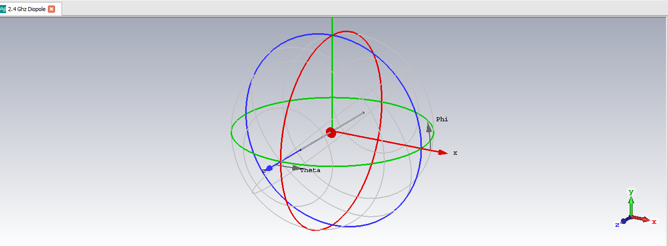
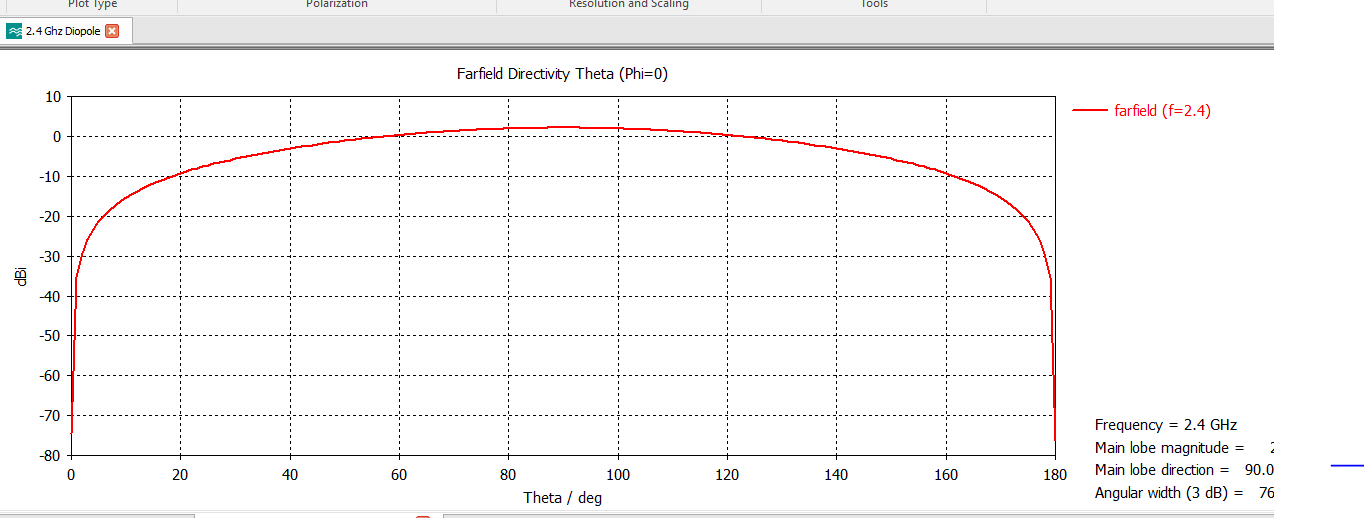
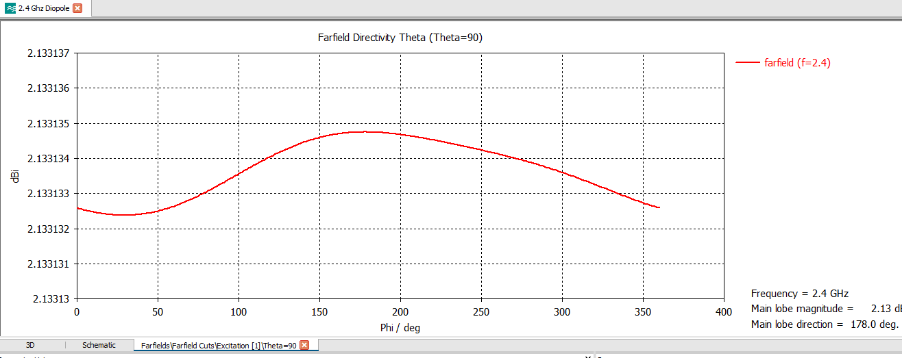
Radiation Pattern of Directivity:
In the field of electromagnetics, the antenna or optical system’s directivity describes the extent to which the radiation it emits is focused in a single direction. It is the ratio of the average intensity of radiation in all directions to the intensity of radiation from the antenna in each direction.
Radiation refers to the reception or emission of a wave front by an antenna, as well as its intensity. In any illustration, the pattern of radiation of an antenna is displayed by the sketch used to depict its radiation. The function and directivity of an antenna can be easily deduced from its radiation pattern.
Field Regions:
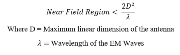
Electromagnetic waves travel into space whenever a transmitter signal is applied to an antenna. With increasing distance from the antenna, the EM field’s properties alter. They are divided into two sections: far-field and near-field regions. The region immediately surrounding the antenna is known as the near field region. The following equation defines it. No measurements are often taken in this area because the fields there are somewhat unpredictable.
The far field region is that which follows the radiative near field. Most of the electromagnetic fields in this region are radiating fields same as the plane waves, the electric and magnetic fields are perpendicular to each other. They are also orthogonal to the propagation direction. The following formula below shows
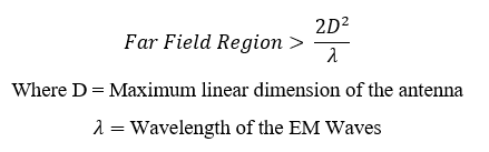
The far field region:
Typically, antennas are utilized to transmit signals in the far-field region, which have a long range. For measurements to be taken in the far field zones, the distance from the antenna must be significantly greater than its size and wavelength.
Simulation and Results
Procedure of Designing a Dipole Antenna
- Open CSD, select a new template. Select MW and RF and OPTICAL.
- Go to antenna and select the antenna from the list.
- Select the wire component from the workflow. We use integral equation for electrically very large antennas select the units according to our requirement dimension in Millimeter Frequency in Gigahertz, Time in nanosecond.
- Select minimum frequency 1.4 and maximum 3.4 because we required to make 2.4gigahertz antenna. Then go to next.
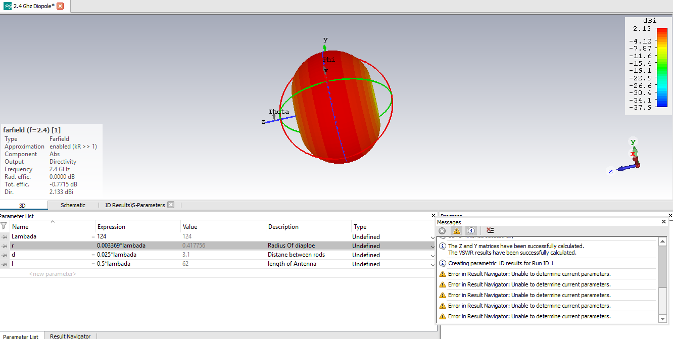
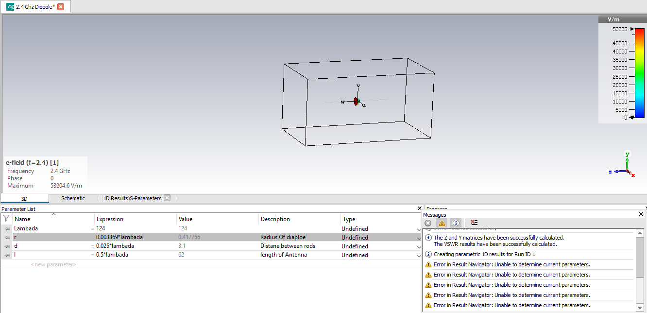
- Then a cube appears in the screen. Now we have to enter the parameter to make the antenna. Now we must enter the parameter to make the antenna. We have the parameter list in the below enter the parameter name and go to macros, go to calculate and the select the calculate the wavelength we have a tab appears in the screen.
- Now enter the desired frequency then ok the tab. The value of lambda appears after we put this value in the expression of lambda in parameter list and the press enter. Other parameter is radius as r and radius of dipole is .00369 multiply the calculated value of lambda.
- Then add the primer between rod 0.025*lambda. the perimeter of length is 0.5*lambda Then go to modeling, go to cylinder then window popups with name of cylinder. We changed the name of cylinder to dipole the outer r which is mentioned in perimeter list. Change the z minimum length/2.
- Material to pec component to antenna.
- Then we go to modeling and select the block then the window popup with name solid 1 charge it with name of brick. Then change the x minimum –r and x maximum +r. y
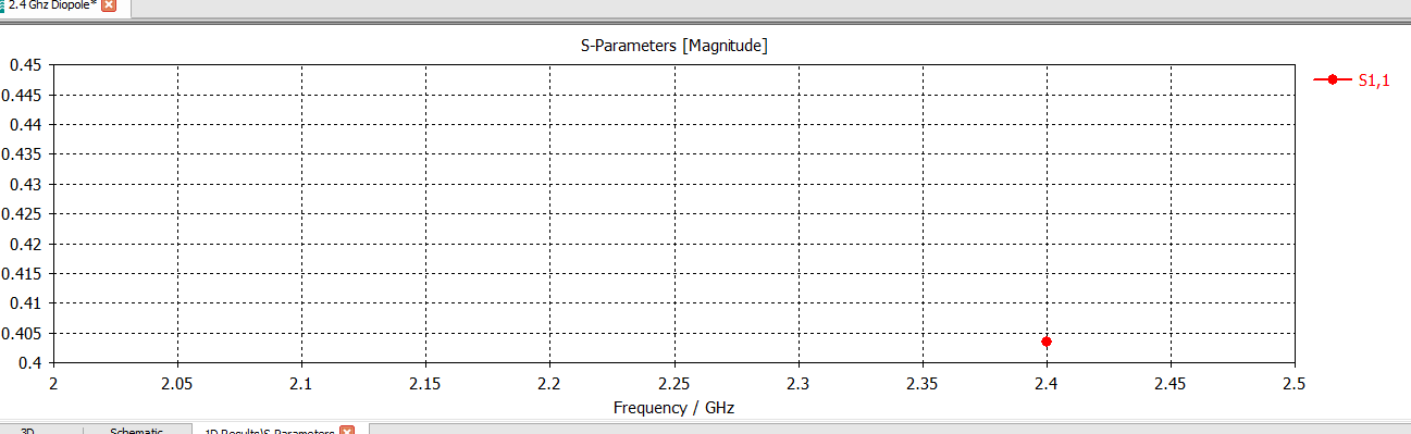
- Minimum –r and y maximum +r. Z minimum is –d/2and Z maximum is +d/2. Then click ok. After clicking ok. Go to the components and select the brick our dipole checks out the select the s parameter. Click ok and we check the boundaries of our dipole. check out the planes and field and then start monitors and then start the simulation then we go to result to finds parameter graphs and we go to field and fiends 2D and 3D result.
Application of Dipole antenna:
- Used in communication system, public safety costal and industrial communication.
- Simple and cost efficient.
- Simple to design and can be reduced and resonated with coil.
- Dipole antenna received stabilize signal
- Dipole antennas (or their derivatives, such as the monopole) are used to power more complex directional antennas such as a horn antenna, corner reflector, or parabolic reflector.
- Omi-directional and provides wide frequency range.
Conclusion
This cep’s major goal was to examine a Dipole antenna’s various antenna properties as they relate to wireless applications. CST Microwave Studio is the simulation software used for easy simulation. The observed results can be put to use in the actual construction of this kind of antenna. The resonant frequency of 2.404 GHz, which is close to 2.4 GHz, is used. The properties of the reflection coefficient are shown by the far field, which was measured at 21.827 dB. The observed bandwidth was 500 MHz, or 0.4779 GHz, which is also suitable for a variety of wireless applications. There are additional parameter scopes that researchers can expand in the future.
Also Read here: