Introduction to passive wireless sensor
In this article, a complete overview of the passive wireless sensor for atmospheric corrosion monitoring is given. There are corrosion sensors based on the variation of DC electrical resistance of metallic wires. During the corrosion process, the chemical compositions of metallic wires change which decreases the conductivity of the wire. To know whether the user should undergo a maintenance procedure or not we used to perform a homogenous corrosion process. Since these are the active sensors so during the monitoring of atmospheric corrosion they indicate the presence of cables. Also, they are not long long-lasting and atmospheric corrosion detection is a long process and thus active sensors are not much reliable. We have a passive wireless corrosion sensor that works on RFID technology and lasts long.
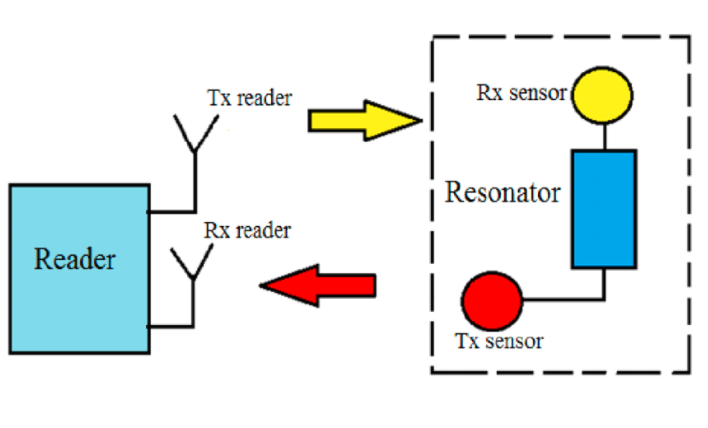
We concentrate on the design of a UHF wireless corrosion sensor that indicates corrosion state via frequency shift rather than amplitude signal variation. The primary reason for this is that in wireless applications, the amplitude is directly affected by the propagation channel (distance between the reader and the tag, reader position, etc.). Following Preradovic and Karmakar’s chipless RFID tag device, we chose to consider a resonator connected to two cross-polarized monopole antennas.
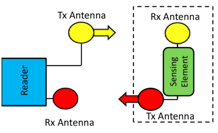
The sensor’s resonator is built on microstrip transmission lines made of the same material as the rest of the mechanical structure being monitored. As a result, it is susceptible to corrosion. The interrogation signal is retrodifused in this system. Cross polarized antennas are used to achieve good isolation between received and transmitted signals (Rx and Tx ports of the reader). This sensor meets the criteria because it is completely passive and does not require any power supply to operate.
Block diagram of system
- The resonator is based on stub resonator device and is produced by physical vapor deposition(PVD) and photolithography techniques.
- We will focus on materails that contain zin alloys because they are widely used in transport companies.
- we use microstrip lines made up of pure zinc.
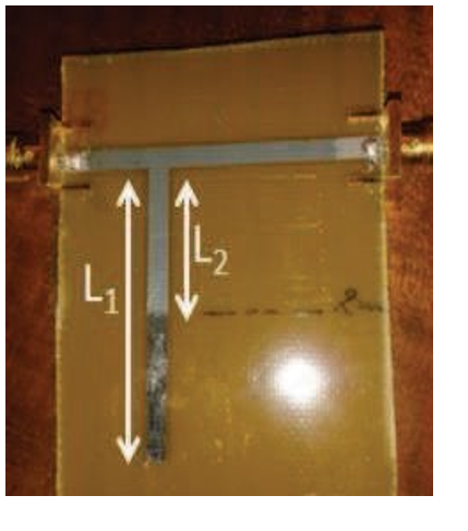
- During the process the stub resonator divides into two parts, the first part is in grey colour it will be protectd from corrosion and the second one is in black color that is affected by the corrosion.
- Electrical corrosion results in a change in the length of the initial stub and, as a result, a resonance frequency shift of the resonator.
- Frequency resonator will act as a binary detector of corrosion
We made zinc resonators with a thickness of about 2 m and used a relatively severe exposure condition to observe the frequency change quickly. The sensitivity of the sensor, on the other hand, can be adjusted by constructing stub devices of varying thicknesses.
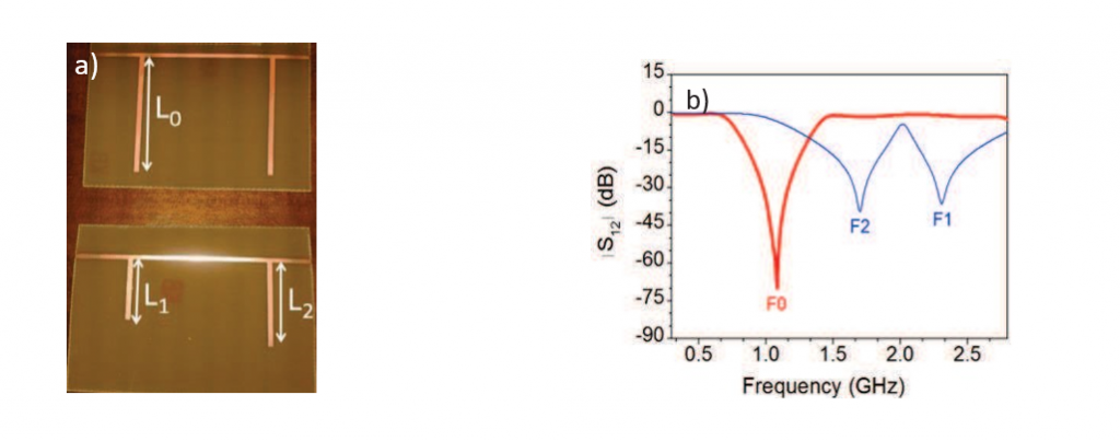
Now we use two states corrosion sensor before and after corrosion, stubs are produced in copper rather than zinc, and the change in their shape simulates the corrosion of unprotected material. The stub on the left side of the multi-resonator has a lower thickness than the second stub and will thus be corroded first.
Before corrosion, as shown in Fig. 3 (b), the device’s resonance frequency is F0, which corresponds to the L0 length of both stubs. After corrosion, the device’s resonant frequencies will be F0 and F1 due to the change in length of L0 to L1, with the second stub remaining unchanged. In a subsequent step, the length of the second stub is reduced, resulting in F1 and F2 frequencies.
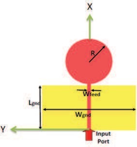
The sensitivity of the sensor to detect a change in frequency and, as a result, a loss of metal is determined by the resonator’s quality factor. For sensor to be sensitive we will use circular monopole antenna
Circular monopole antennas have a simple layout and an extremely wide bandwidth. The antenna we have used is built on a FR4 substrate. On the top layer, it has a 50 microstrip feed loaded with a circular disc. On the bottom layer, there is a ground plane that stops near the disc. In our application, we perform a thorough analysis within a frequency range ranging from 0.8 GHz to 2.8 GHz in order to design a system that is compatible with standard ISM bands.
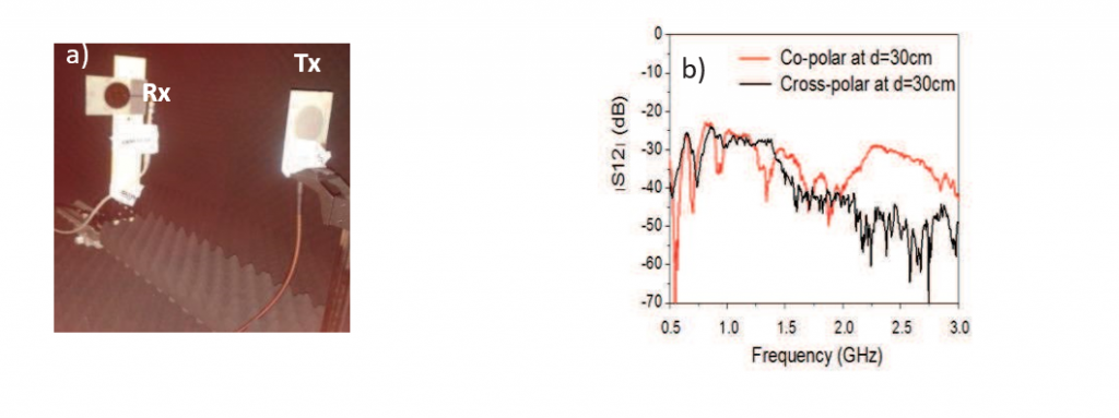
The goal is to improve isolation between the TX and RX channels by using cross-polarized antennas. As shown in (a), the transmitted amplitude of the monopoles in both co-polar and cross-polar configurations was measured in the anechoic chamber at different distances (5 cm / 30 cm) by a network analyzer (PNA N5222A). The results for a separation distance of 30 cm between the two antennas are shown (b). At 2 GHz, the transmission S12 parameter exhibits a good cross-polar isolation of about 20 dB, which is required for a robust isolation between transmitted and received signals. Isolation is poor at low frequencies (0.8 GHz).
Conclusion
The design is a fully passive wireless corrosion sensor based on the coupling of wideband antennas and an active multi-resonator is presented in this article. By interrogating the sensor with a multifrequency signal, the variation in the magnitude of the multi resonator can be detected and the state of corrosion deduced. As demonstrated in this study, the key factor in the realization of such a sensor is the isolation between the TX and RX signals, which can be improved by taking temporal isolation into account.
Future work
Corrosion sensing is critical for monitoring and protecting the health of materials as well as controlling the maintenance costs of corrosion-prone materials used in a variety of industries. Because of pipelines and downhole applications, the petroleum industry bears the brunt of corrosion costs among various industries. Passive wireless atmospheric corrosion sensors sense the corrosion in the environment and after sensing we can find out the solution that how to remove but the first step is to figure out which we can do with passive sensors. Passive sensors are the best because they are long-lasting and need no source to operate.
Also read here
https://eevibes.com/blog/how-to-select-which-printed-circuit-board-is-best-for-your-design/