Table of Contents
Introduction
How to Design Counters Using Sequential Circuits? We already know that counters can be implemented like cascaded flip-flop stages and some gate logic where each stage divides a number of incoming pulses by two. To keep our example simple, we’ll choose a small counter size, but also show how the design can be extended to larger sizes. Specifications for the counter is:
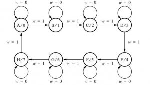
- The counting order is 0, 1, 2,… 6, 7, 0, 1,…
- There is an input signal w.
The value of this signal is taken into account at each clock cycle. If w = 0, the current count remains the same; if w = 1, the count is incremented. A counter can be designed as a synchronous sequential circuit using design techniques introduced in previous sections
State Assignment
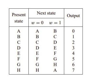
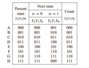
Three state variables are needed to represent eight states. Let these variables, denoting the current state is called y2, y1 and y0. Let Y2, Y1 and Y0 denote the corresponding next state function. The most easiest state assignment is to encode each state with a binary number that the counter have to provide output in that state. Then the desired output signals will be the same as the signals representing the state variables. This leads to the table of assigned state:
After assigning the A,B,….H to binary numbers.
The last step in the design is the selection of the type of flip-flops and the derivation of expressions that implement and control the flip inputs. The easiest option is to use type D flip flops. We are going to follow this approach. Then we will show the alternative of using JK type flip-flops. In both cases, the flip-flops must be edge-triggered to ensure that it only takes one transition place during one clock cycle.
Implementation using D-flipflop
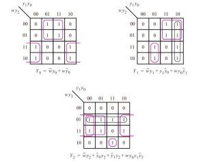
When using D-type flip-flops to implement a finite state machine, each next-state function Yi, is connected to the D input of a flip-flop that implements the specific state variable yi. the next state functions are derived from this information. By using K-maps we get the following results:
D0 = Y0 = wy0 + wy0
D1 = Y1 = wy1 + y1y0 + wy0 y1
D2 = Y2 = wy2 + y0 y2 + y1 y2 + wy0y1y2
It is not clear how to expand this range implement a larger counter because no clear pattern is discernible in the expressions for D0, D1 and D2. However, these expressions can also be written as:
D0 = wy0 + wy0
= w ⊕ y0
D1 = wy1 + y1 y 0 + wy0 y1
= (w + y0) y1 + wy0 y1
= wy0y1 + wy0 y1
= wy1 ⊕ y1
D2 = wy2 + y0 y2 + y1 y2 + wy0 y1 y2
= (w + y0 + y1) y2 + wy0 y1 y2
= wy1 y1 y2 + wy0 y1 y2
= wy0 y1 ⊕ y2
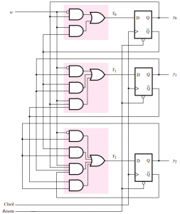
Circuit diagram for the counter implemented with D flip-flops
Implementation using J-K flipflop:
JK flip flops are an attractive alternative. Using these flip-flops to implement the sequential circuit requires the derivation of the J and K inputs for each flip flops. The following check is required:
- If a flip-flop is in the state 0 it has to remain in the state 0, then the J = 0 and K = d (where d means that K could be equal to either 0 or 1). • If the flip-flop in state 0 changes its state into 1, then J = 1 and K = d.
- If a flip-flop in state 1 is to remain in state 1, then J = d and K = 0.
- If the flip-flop is in state 1 is to change to state 0, then J = d and K = 1.
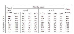
Following these instructions, we can create a truth table that specifies the desired values of inputs J and K for the three flip-flops in our design. a modified version of the state-assigned table with input functions J and K included. To see how this table is derived, consider the first row in which the current state is y2y1y0 = 000. If w = 0, then the next state is also Y2Y1Y0 = 000. the value of each flip-flop is 0 and should remain 0.
This means that checking J = 0 and K = d for all three flip-flops. We continue in the first line, if w = 1, the next state will be Y2Y1Y0 = 001. So flip-flops y2 and y1 still remain at 0 and have control J = 0 and K = d. However, flip-flop y0 must change from 0 to 1, which is achieved with J = 1 and K = d.
The rest of the table is derived in the same way by considering each gift state y2y1y0 and providing the necessary control signals to achieve the new state Y2Y1Y0. A state-assigned table is essentially a state table in which each state is encoded state variables.
When D flip-flops are used to implement the FSM, the next state items in the state-assigned table correspond directly to the signals that must be applied to D inputs. This does not apply if another type of flip-flops is used.
The table that gives status information in the form of flip-flop inputs that must be “excited” to cause the transitions to the next states are usually called the excitation table. Wake-up table shows how JK flip-flops can be used.
In many books the term excitation table is used even when D flip-flops are involved, in which case it is synonymous with state-assigned table. Once has been derived, it provides a truth table with inputs y2, y1, y0 and w and outputs J2, K2, J1, K1, J0 and K0. We can then derive expressions for
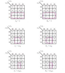
J0 = K0 = w
J1 = K1 = wy0
J2 = K2 = wy0 y1
The k-map of the expression is given below:
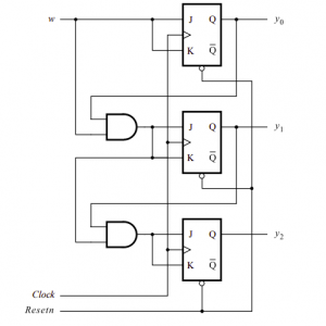
The logic diagram is given below:
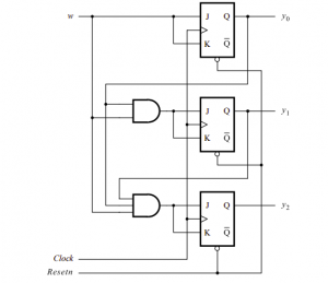
Using the factored form, the counter circuit can also be implemented. Note that in this circuit all the steps (except the very first one) look the same. Also note that this circuit has the same structure like the previous circuit because it connects the J and K inputs of the flip-flop together they change the flip-flop to a T flip-flop.
What are the Counters ? UP Counter Operation
Also read here
- What are the CMOS Logic Gates?
- What is the magnitude comparator circuit? Design a 3 bit magnitude comparator circuit
- What are the synchronous counters? Explain with an example.
- what are the half adder and full adder circuits?
- what are the half subtractor and full subtractor circuits?
- How to design a four bit adder-subtractor circuit?
- What are number systems in computer?
- Discuss the binary counter with parallel load? Explain its working with an example
- how to draw state diagram of sequential circuit?
- How to simplify a Boolean function using Karnaugh map (k-map)?
- What are the flip flops and registers in digital design?
- Define fan-in, fan-out, CMOS and TTL logic levels
- what is the Canonical form representation of Boolean function?
- What is difference between latches and flip flops?