Circuit Theory at High Frequency
Why Circuit Theory Fails at High Frequency? Circuit theory, which is based on the principles of Kirchhoff’s laws and Ohm’s law, is a powerful and widely used tool for analysing electrical circuits at low to moderate frequencies. However, it does have limitations when applied to high-frequency circuits, and these limitations arise from several factors:
Parasitic Elements:
At high frequencies, the parasitic elements of components, such as capacitance, inductance, and resistance, become significant. These parasitic elements can no longer be ignored and must be included in circuit models. For example, the parasitic capacitance of a wire or a component can cause unwanted capacitance coupling between different parts of the circuit, affecting its behaviour.
Example
Parasitic capacitance refers to the inadvertent or undesired capacitance that arises within an electronic or electrical circuit due to the proximity and inherent characteristics of components, conductors, or traces, often resulting in unintended capacitive effects.
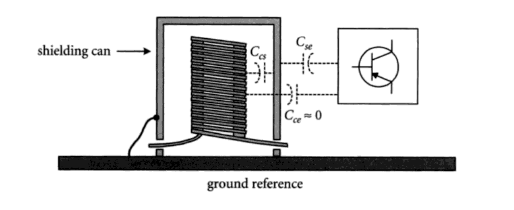
Parasitic capacitance at high frequencies is a critical consideration in the design and performance of electronic circuits and systems. This phenomenon refers to the unintended capacitance that arises due to the inherent properties and geometries of components, traces, and conductors in a circuit when it is subjected to high-frequency signals. Understanding and managing parasitic capacitance is essential because it can have a substantial impact on signal integrity, circuit stability, and overall system functionality.
Key points to consider about parasitic capacitance at high frequencies include:
Proximity Effects: At high frequencies, even small gaps between conductors can act as capacitors, as electric fields are more concentrated. These unintended capacitors can introduce impedance and affect signal propagation.
Signal Integrity: Parasitic capacitance can lead to signal distortion and loss, especially in high-speed digital circuits and RF (Radio Frequency) systems. It can cause signal reflections, phase shifts, and attenuation, degrading the quality of transmitted or received signals.
Power Consumption: Parasitic capacitance can also increase power consumption in integrated circuits. Charging and discharging these capacitances require energy, which can be a significant concern in battery-powered devices.
Frequency Dependency: The impact of parasitic capacitance becomes more pronounced as the operating frequency of a circuit increases. Engineers must account for this capacitance when designing high-frequency circuits, as it can affect the intended circuit behavior.
Mitigation Techniques: Engineers employ various techniques to mitigate the effects of parasitic capacitance. These include careful layout and routing of traces, the use of shielded cables, and the selection of components with lower parasitic capacitance characteristics.
Simulation and Modeling: Advanced simulation tools and modeling software are invaluable for analyzing and predicting the effects of parasitic capacitance at high frequencies. They enable engineers to optimize circuit designs and minimize undesirable capacitive effects.
Balancing Act: Managing parasitic capacitance involves a trade-off between factors like component size, trace length, and signal speed. Engineers must strike a balance to achieve the desired circuit performance while minimizing parasitic capacitance.
Transmission Line Effects:
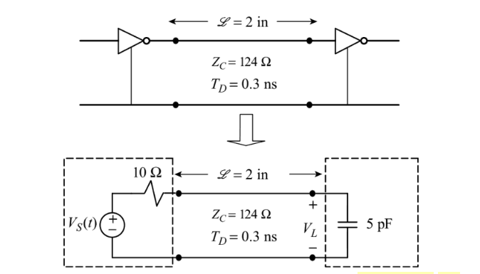
At high frequencies, the physical dimensions of conductors and traces on a circuit board become comparable to the wavelength of the signals being carried. This leads to transmission line effects, where the behaviour of the circuit is more accurately described by transmission line theory, which accounts for impedance mismatches, reflections, and wave propagation effects. Circuit theory assumes ideal connections without transmission line effects, which can lead to incorrect predictions at high frequencies.
Non-Ideal Components:
Real-world components are not ideal at high frequencies. For instance, an inductor may exhibit parasitic capacitance, and a capacitor may have parasitic inductance. These non-ideal characteristics can significantly affect the performance of the circuit at high frequencies and are not accounted for in basic circuit theory.
Skin Effect and Dielectric Loss:
At high frequencies, the skin effect becomes more pronounced, causing the current to concentrate near the surface of conductors. This leads to increased resistance and can affect the performance of components like resistors and inductors. Dielectric materials in capacitors can also exhibit losses at high frequencies, which are not considered in simple circuit models.
Skin Effect
In the field of electrical engineering, the skin effect is a phenomenon observed in high frequency alternating currents. This is manifested in the tendency of these currents to concentrate near the outer surface of a conductive material. This occurrence causes the current flow to be limited to only a fraction of the total cross-sectional area of the material, and consequently increases the resistance of the conductor.
Due to the presence of the skin effect, the induction heating can be limited exactly to the surface of the material. This localization of heat can be managed by choosing an appropriate inductor coil configuration. The degree of heating can be precisely controlled (as demonstrated in the practice of induction heating). It should be noted that the intensity of the skin effect becomes more pronounced with magnification of frequency.
Electromagnetic Radiation:
At high frequencies, circuits can behave as antennas and radiate electromagnetic energy. This is particularly important in RF (radio frequency) and microwave circuits, where energy loss through radiation can be significant. Circuit theory does not account for radiation effects.
Wave Nature of Signals:
At high frequencies, the wave nature of signals becomes more pronounced, and concepts like phase, wavelength, and impedance matching become critical. Circuit theory, which is based on lumped-element models, is not well-suited for describing these wave phenomena accurately.
To analyze circuits at high frequencies, more advanced techniques, such as RF circuit analysis, microwave engineering, and electromagnetic field simulation, are often employed. These methods take into account the complex behaviors and interactions that arise at high frequencies and are necessary for designing high-frequency and high-speed electronic systems accurately.