
What are the Encoder Circuits?
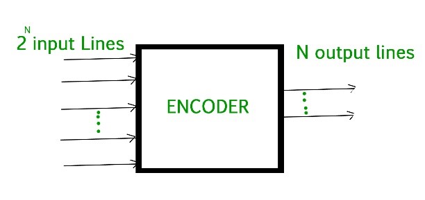
What is the Encoder in Digital Circuits? Encoder is an combinational circuit that performs the function of converting Decoder. It has 2 ^ n input lines and ‘n’ output lines, after which it enters data from input 2 ^ n into n-bit code. It will send the same code to the input, which is a powerful Tool. Next, the encoder inserts 2 ^ n input lines with ‘n’ pieces.
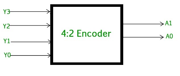
4 to 2 Line Encoder Circuit
The 4 to 2 Encoder contains four inputs Y3, Y2, Y1 & Y0 and two outputs A1 & A0. At any time, as it was one of these 4 things that could be a ‘1’ in planning to request a dual product-specific code. The figure below comes from a realistic image of the 4 to 2 encoder:
Truth Table for 4 to 2 Line Encoder
The 4 to 2 line encoder Truth Table is as follows:
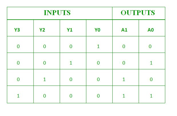
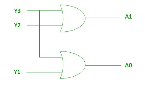
The logical expression for A1 and A0:
A1 = Y3 + Y2
A0 = Y3 + Y1
The two above Boolean A1 and A0 operations can be performed using dual inputs or gates:
Video Lecture for Encoders
8 to 3 line Encoder (Octal to Parallel):
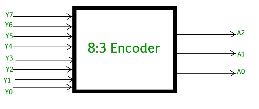
The 8 to 3 Encoder or octal to Double encoder contains inputs 8: Y7 to Y0 and 3 yields: A2, A1 & A0. Each input line compares with each octal number and three outputs produce a corresponding binary code.
The figure below shows the octal sign of encoding:
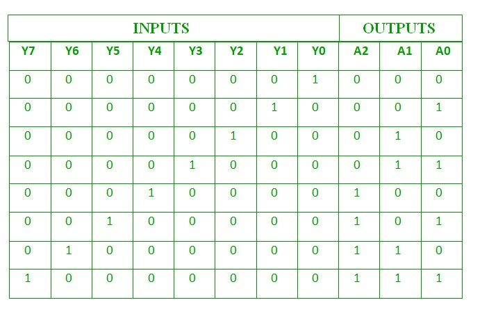
Truth Table for 8 to 3 Line Encoder
The truth table for 8 to 3 encoder table is shown below:
Logical expression A2, A1 and A0:
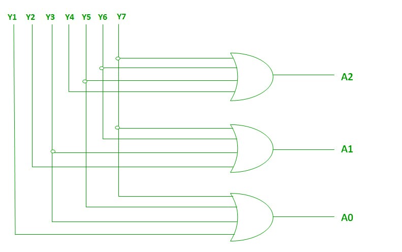
A2 = Y7 + Y6 + Y5 + Y4
A1 = Y7 + Y6 + Y3 + Y2
A0 = Y7 + Y5 + Y3 + Y1The above two functions of Boolean A2, A1 and A0 can be performed using four inputs or gates:
How to Design a Decimal to BCD Encoder Circuit?
Decimal to BCD Encoder:
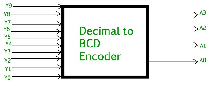
Decimal in BCD Encoder – Binary encoder decoder often includes 10 input lines and 4 crop lines. Each entry line compares with each decimal number and 4 fruits compared to the BCD code. This coding validates the decoded details of the code as input and incorporates it into the BCD product available in the production line.
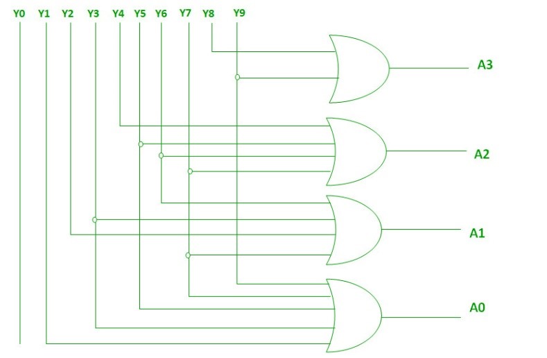
The figure below comes from a decent picture of BCD encoding:
The truth table for decimal to BCD encoder is underneath shown
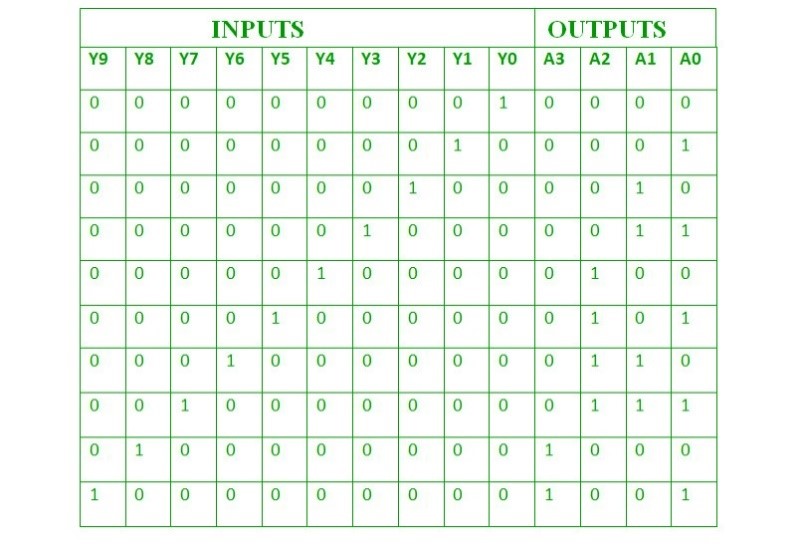
The Logical expression for A3, A2, A1 and A0:
A3 = Y9 + Y8
A2 = Y7 + Y6 + Y5 +Y4
A1 = Y7 + Y6 + Y3 +Y2
A0 = Y9 + Y7 +Y5 +Y3 + Y1
The above two Boolean functions can be shown using OR gates:
16 to 4 Line Priority Encoder
Similarly, a 16 to 4 encoder can be created using six to 2 encoders. 4 to 2 encoders are associated with 16 inputs and 8 yields are also associated with 4 to 2 codecs, producing 4 outputs.
What is the Priority Encoder?
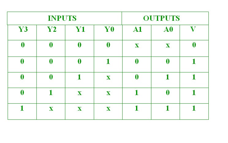
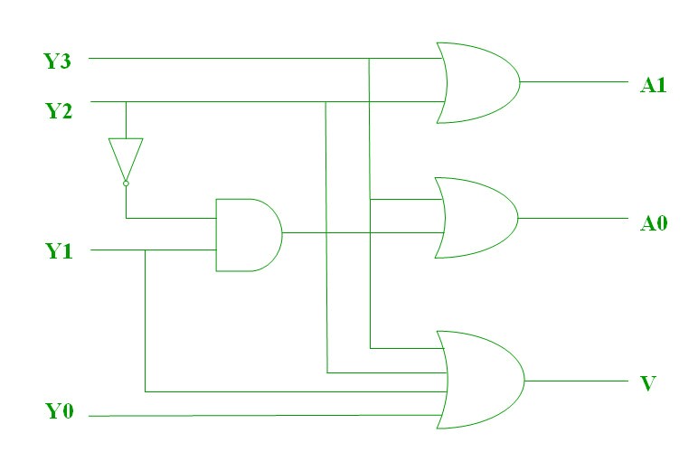
Priority encoder has 4 input: Y3, Y2, Y1 & Y0 and 2 output: A1 & A0. Here, input, Y3 has a very high value, while input, Y0 has a much reduced priority. In this case, exactly in the case where more than one input is ‘1’ at the same time, the yield will be a binary code compared to the input, priority.
The true table for standard encoder is below:
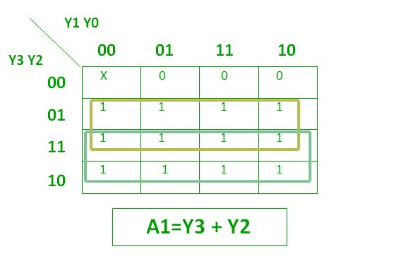
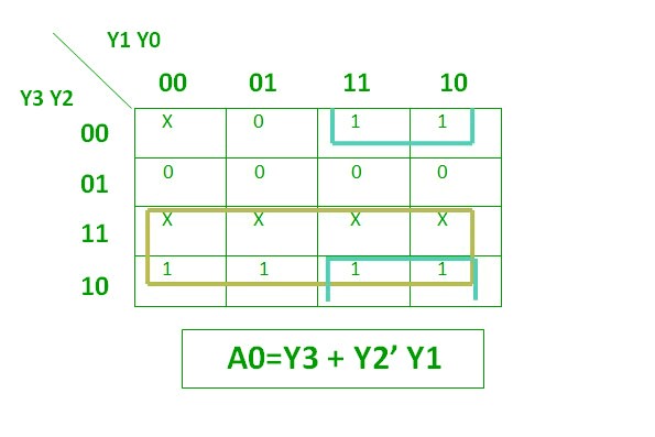
The above two Boolean functions can be shown as:
What is the Positional Encoder?
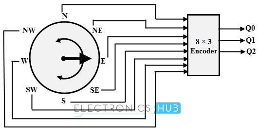
Attractive climate management is another common way to incorporate needs. Such controls are used for automatic arm rotation and movement. In such cases, changes in transcription or compass accuracy have moved to higher-quality code. At that point the code goes into the computer so that the travel details are provided.
Below this figure appears a specific compass code that changes over 8 to 3 crop fields. For this type of installation – output setup, the 74LS148 IC used an 8-to-3 line need encoder. To indicate the exact location of a compass, a large reed strand is used.
Keyboard Encoders:
Accept that the QWERTY keypad is a microcomputer interface so the computer should use 104 console keys that they can use at any time such as pressing a single key such as High or LOW. 104 organizations are computer-generated (if not well-organized), however it can be an effective way to integrate them using a codec. Using this encoder, each letter or key is encrypted with a standard 7-bit ASCII (0-127 decimal) code for all 104 keys or personal keys. Then insert the 7-bit BCD code into the computer. Another type of console has 20,
74C923 keys. In addition these codes give the office the need to, when two buttons are pressed at the same time, provide the most important input.
Decreased standard input codes:
There is an ambiguity, in which all encoding equals zero. If more than one input has a solid Tall, then the encoder produces the output, which may not be the correct code. Therefore, to overcome these problems, we must provide the requirements for each code. At that point, the encoder yield will be (code compared to Tall’s powerful input, which is very important.
What are the applications of Encoders?
Standard electrical circuit encoders are used in all computer programs. Encoders are used to specify decimal values in binary settings to create dual power such as magnification, subtraction, multiplication, etc. Some applications, especially Priority Encoders, may install barriers to chip applications.
Priority Encoder applications
As compared to the standard advanced encoder, a priority encoder is most commonly utilized in a few applications. A bigger priority encoder is planned by cascading the a few priority encoders. In this manner, this sort of encoders is utilized to diminish the number of associations required in a specific application in which there are different inputs are present.
Video Lecture for Priority Encoder Circuits
Also read here
-
What are the CMOS Logic Gates?
-
What is the magnitude comparator circuit? Design a 3 bit magnitude comparator circuit
-
What are the synchronous counters? Explain with an example.
-
what are the half adder and full adder circuits?
-
what are the half subtractor and full subtractor circuits?
-
How to design a four bit adder-subtractor circuit?
-
What are number systems in computer?
-
Discuss the binary counter with parallel load? Explain its working with an example
-
how to draw state diagram of sequential circuit?
-
How to simplify a Boolean function using Karnaugh map (k-map)?
-
What are the flip flops and registers in digital design?
-
Define fan-in, fan-out, CMOS and TTL logic levels
-
what is the Canonical form representation of Boolean function?
-
What is difference between latches and flip flops?