Vacuum soldering can reduce gas trapped inside molten solder joints, but the vacuum level alone does not determine the result. A reliable process depends on the coordination of temperature, pressure, timing, atmosphere, solder paste, printed deposit, board design, transport, cooling, and measurement. If one variable is optimised without considering the others, voids may remain—or new defects such as solder splashing, component movement, excessive residue, disturbed joints, or unnecessary cycle time may appear.
The most important principle is simple: apply vacuum inside a proven soldering window while the solder is molten and the assembly remains stable. Verify the result with thermocouples, X-ray inspection, process records, and repeatability studies.
Why Vacuum Soldering Requires a Process Window

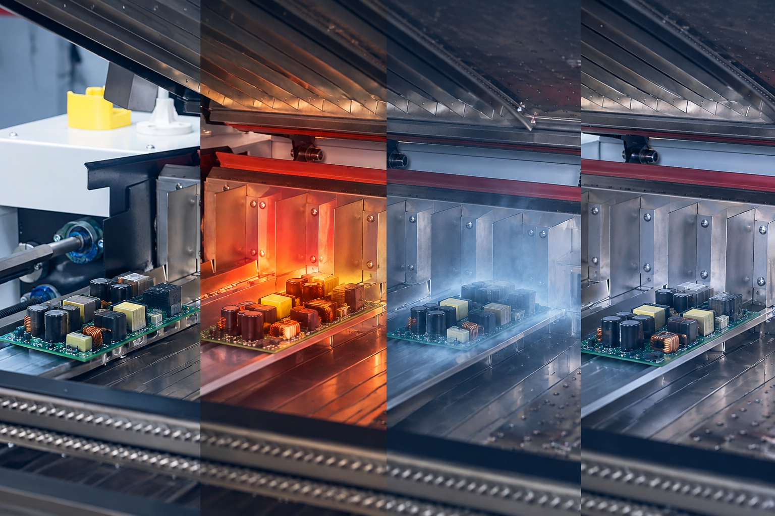
During reflow, flux chemistry activates, solvents and reaction products evolve, oxides are removed, solder particles coalesce, and the alloy becomes liquid. Some gases escape naturally, while others become trapped by package geometry, pad design, solder volume, surface tension, and the timing of solder coalescence. A vacuum stage lowers the surrounding pressure so trapped gases can expand and leave the joint before solidification.
Aggressive pressure reduction is not automatically better. Evacuating too early can disturb paste or flux; evacuating too late leaves little time before solidification; venting too quickly can move components or molten solder. Vacuum soldering is a linked pressure-temperature-time process, not one machine setting.
1. Temperature Profile Before the Vacuum Stage
Ramp Rate and Preheat Balance
The heating profile must prepare the entire assembly for a stable vacuum event. A controlled ramp allows the PCB, packages, pads, and solder deposits to heat without excessive thermal gradients. Heavy copper, shields, power packages, large thermal pads, carriers, and thick multilayer boards may lag behind small components. If the board enters the vacuum chamber with large temperature differences, some joints may be fully molten while others are only beginning to reflow.
Set ramp and preheat from the solder paste supplier’s guidance and a measured profile on a representative loaded board. Place thermocouples on high- and low-mass locations, especially the joints whose voiding matters most. Product temperature—not oven air temperature—confirms the process.
Soak, Flux Activation, and Volatile Release
The soak region affects temperature balance and flux activation. Too little soak can leave thermal differences; too much can consume flux activity or change residue behavior. Vacuum cannot compensate for poor activation, so evaluate soak together with wetting, residue, solder spread, and X-ray results.
Peak Temperature and Time Above Liquidus
The joint must remain molten long enough for wetting and gas removal, but unnecessary heat exposure can stress the PCB and components. The critical question is not simply the oven’s peak setting. It is the actual joint temperature when evacuation starts, throughout the vacuum hold, and when pressure is restored.
The vacuum cycle consumes part of the available molten-solder window. Process engineers should confirm that the target joints are above liquidus during the useful extraction period without extending total thermal exposure beyond the limits of the solder paste, packages, laminate, finishes, and internal quality rules.
2. Vacuum Pressure and Evacuation Depth
Define the Pressure at the Chamber, Not Only at the Pump
Vacuum performance should be measured and controlled where it represents the chamber process. Pump capability, pipe length, filters, condensate, seals, flux contamination, valve behavior, chamber volume, and product loading can all affect the pressure curve seen by the PCB. A pump specification does not prove that the same pressure is reached consistently in production.
The target pressure must be selected through testing. Lower pressure can increase the driving force for gas expansion, but it may also increase process sensitivity, cycle time, and the risk of disturbing molten solder or components. The best setting is the lowest practical pressure that produces a stable quality improvement without creating new defects.
Pressure Stability and Repeatability
The chamber should reach and hold its target consistently. Trend evacuation time, minimum pressure, stability, and venting time. Gradual change may indicate seal wear, pump condition, contaminated filters, flux buildup, valve problems, or sensor drift.
For equipment selection, Vacuum Reflow Soldering should be evaluated as an integrated system that includes heating, chamber control, segmented transport, cooling, software records, maintenance access, and facility requirements—not only as a quoted ultimate vacuum value.
3. The Timing of Vacuum Application
Start After the Relevant Joints Are Fully Molten
Vacuum should normally begin only after the solder structures being controlled have reached a stable molten condition. Starting too early may promote spattering, solder displacement, disturbed flux behavior, or incomplete coalescence. Starting too late reduces the time available for bubbles to expand, move through the solder, and escape before solidification.
Base the trigger on the slowest critical joint, not the easiest thermocouple point—especially for large exposed pads, power modules, bottom-terminated components, and uneven copper distribution.
Coordinate Transport and Chamber Entry
In an inline system, transfer time, rail stability, board spacing, chamber availability, conveyor speed, and thermal loss all affect joint temperature at evacuation. Treat queue control and segmented transport as process parameters, with defined rules for alarms, bypasses, upstream stops, and line recovery.
4. Evacuation Rate, Hold Time, and Venting Rate
Evacuation Rate
The rate of pressure reduction controls how rapidly trapped gases expand. A very fast pull-down may remove gas efficiently, but it can also make the process more violent. A staged or controlled pressure curve may provide a better balance for sensitive components, large solder deposits, or assemblies vulnerable to movement.
Establish the curve using actual defect evidence. Review X-ray images for void area, position, clustering, joint coverage, and board-to-board consistency. A lower average is not enough if large voids remain in critical thermal paths.
Vacuum Hold Time
The hold must be long enough for gas to migrate out of the molten joint after the target pressure is reached. Extending it indefinitely is not useful: the board remains at elevated temperature, flux behavior continues to change, and throughput declines. The correct hold time is the shortest repeatable interval that meets the defined joint-quality target across normal product variation.
Controlled Venting
Pressure recovery deserves the same attention as evacuation. Rapid venting can disturb components and liquid solder. Control gas cleanliness, flow direction, and venting rate, and release the board only after pressure and assembly stability meet the transfer condition.
5. Atmosphere and Oxygen Control
Vacuum and nitrogen address different mechanisms. Vacuum helps remove trapped gas; nitrogen limits oxidation and can improve wetting margins. Some products may benefit from both, while others can meet quality targets with vacuum in a different atmosphere. Nitrogen should not be added automatically without evidence that oxygen control improves the specific assembly.
If nitrogen is used, monitor purity or residual oxygen at a meaningful location. Leaks, exhaust balance, loading, and flow settings can change the real atmosphere, so include analyzer calibration, alarms, and records in the control plan.
6. Solder Paste, Stencil Deposit, and Pad Design
Paste Chemistry Must Match the Vacuum Process
Solder pastes differ in solvent system, flux activity, residue behavior, metal loading, slump, wetting, and tolerance for vacuum exposure. A paste described as low-void may still require a carefully matched profile and deposit design. Any change in paste manufacturer, alloy, lot, storage condition, thawing, mixing, or open time can alter outgassing and reflow behavior.
Qualify the paste with the actual finish, termination, atmosphere, vacuum sequence, and cleaning requirement. Conventional-reflow behavior does not guarantee identical results under changing pressure.
Printing and Aperture Design Still Matter
Vacuum cannot correct inconsistent print volume, blocked apertures, poor stencil release, excessive paste, misregistration, or an unsuitable thermal-pad aperture pattern. Window-pane or segmented apertures are often considered for large exposed pads because they can create gas escape paths and control solder volume, but the correct geometry depends on package design and reliability requirements.
Track stencil cleanliness, paste volume, alignment, and inspection data. When voiding changes, confirm printing before changing the vacuum recipe.
7. PCB, Package, Carrier, and Loading Conditions
Board thickness, copper distribution, surface finish, solder mask geometry, via-in-pad structure, package stand-off, component termination, moisture condition, and carrier design all affect heating and gas escape. Two boards with the same external size can require different profiles if their thermal masses or package structures differ.
Panel spacing and chamber loading also matter. Do not apply a one-board qualification to a full carrier without verification. Control orientation, spacing, support, carrier mass, component height, and chamber capacity. If the product mix changes frequently, learn more about standard, nitrogen, and vacuum platforms before choosing the process route.
8. Cooling After Vacuum
Once pressure is restored, cooling determines when the solder solidifies and how long the assembly remains at elevated temperature. Cooling that begins too early or unevenly can interfere with joint formation; cooling that is too slow can extend the thermal cycle and reduce line capacity. The cooling method should maintain board support and airflow consistency without shifting components.
Measure cooling on the product, especially on heavy copper and large thermal interfaces. Record heating, vacuum, venting, and cooling as one continuous recipe.
9. Monitoring, Calibration, and Maintenance
Record the Complete Pressure-Temperature Cycle
A useful record includes recipe identity, board type, transfer timing, zone settings, profile version, pressure curve, evacuation, hold and venting times, atmosphere data, alarms, and inspection result.
Calibrate the Sensors That Drive Decisions
Check temperature sensors, profilers, pressure sensors, oxygen analyzers, conveyor speed, and time controls on a defined schedule based on usage, risk, guidance, and maintenance history.
Control Flux Contamination and Seal Condition
Flux vapor and condensate can contaminate piping, filters, pumps, valves, and chamber surfaces. Base preventive maintenance on operating hours, flux load, pressure trends, seal condition, and inspection—not the calendar alone.
How to Develop a Stable Vacuum Soldering Recipe
Start with a conventional thermal profile that produces sound wetting and complete reflow. Instrument the slowest and fastest critical joints. Add a conservative vacuum cycle while the target solder structures remain molten. Then adjust one parameter family at a time: vacuum start, pressure curve, minimum pressure, hold, venting, atmosphere, or cooling.
Use representative boards and more than one successful sample. Inspect by X-ray and add cross-sectioning, electrical, thermal, or reliability testing where risk justifies it. Define acceptance by package and function, then challenge the recipe with expected production variation.
Frequently Asked Questions
Is the lowest possible vacuum always best?
No. The best pressure is the one that produces repeatable joint improvement without causing solder disturbance, component movement, unnecessary thermal exposure, or excessive cycle time. It must be validated on the actual assembly.
When should the vacuum cycle begin?
It should begin after the critical solder joints are fully molten and before they start to solidify. Thermocouple data and transfer timing are needed to identify that window for each board design.
Can vacuum fix high voiding caused by poor printing?
It may reduce some trapped gas, but it cannot correct excessive or inconsistent paste volume, blocked apertures, poor alignment, unsuitable aperture design, contamination, or unstable print release. Printing should be checked first.
Does every vacuum reflow process need nitrogen?
No. Nitrogen is a separate process choice for oxidation control. Its value depends on solder paste, finishes, package design, wetting margin, residue requirements, and the measured results of the assembly.
Final Checklist
Before release, document the product profile, vacuum start, evacuation rate, minimum pressure, hold, venting, atmosphere, print deposit, loading, transport, cooling, and inspection plan. Confirm calibration, maintenance limits, alarm responses, and capability across normal variation.
Vacuum soldering succeeds when the complete process window is controlled. The objective is not to reach the most extreme pressure or the longest hold. It is to create a repeatable, measurable sequence that removes gas while the solder is molten, preserves wetting and component position, and delivers joint quality that remains stable over time.