what is the power conditioning system?
what is the power conditioning system? Since its inception in 1960, the advancement in the spacecraft design has increased exponentially. Today’s spacecraft are far more capable than those of past years, consolidating multiple missions into a single space platform. This evolving accommodation however, is not without a price. Current satellites are ever increasing in complexity, design times, and, perhaps most significantly, cost. As a consequence of this, it was not possible to inject the satellites studies practically in the academic courses because of the difficulties associated with manufacturing the satellites and the enormous budget incorporated with those projects. Such difficulties have encouraged the world leaders in space technology, including the US and Europe to focus their efforts on smaller satellites that can perform missions traditionally assigned to large/medium satellites and hence the concept “Student satellite” arises.
Although the Student satellites appear as smaller versions of the satellites, they are not merely a scaling of larger satellite design and capability, but it’s a complete renovation of current satellite convention. Student satellites are ideal as space development projects for universities around the world. In addition to their significant role in introducing the students to a realistic and practical spacecraft design and mission launch process, Student satellites provide a low-cost platform for testing and space qualification of the next generation of small payloads in space.
All over the world, public/private sector and academia collaboration brings advancements and breakthrough in the technological dimensions. However, in Pakistan, this type of collaboration is rare. Joint ventures with industry and universities are essential to bring Pakistan at par with other nations of the world in the field of science and technology. It will not only produce cost-effective solutions for the challenging problems but will also contribute towards professional grooming of the future workforce of the country.
Over the last two decades, there has been a considerable increase in the use of satellite based technologies such as vehicle navigation using GPS, long distance phone calls, Digital Video Broadcasting, Satellite Phone and weather forecast etc. This urges for having more satellite experts and extensive R&D activities both at industry and academia.
The international space agencies are providing technical and financial help to the universities in this regard. Due to complex technology and knowledge along with higher cost involved, satellite development by universities, on their own, had been rare. However, in recent past years, advancements in miniaturized devices and low cost launch opportunities has made it possible for academia to design, develop and launch small satellites into space. One of the biggest advantage of which is a very low cost satellite design by employing COTS technology and involving academia workforce. A number of programs are proposed and successfully employed in different parts of the world in which universities are directly engaged in small satellite designing, manufacturing, and launching.
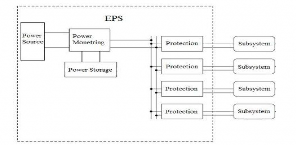
The various equipments on board the Student satellite need to be supplied by the electric power. Thus, the Student satellite needs a reliable power system that is capable of handling the task of providing the needed power for each subsystem in the Student satellite. The Student satellite Electrical Power System aims to provide conditioned power for the Student satellite which involves continuous power generation for supplying the Student satellite, power storage for supplying the Student satellite when the main power generation cannot, monitoring the power to be distributed and protection of the Student satellite in case of a fault situation. The parts of the EPS are shown in figure
The efficiency of the solar cells is determined by the doping characteristics of the semiconductors. When doping the semiconductors, it is important to either have an excess of positive charged carriers (p-type) or a surplus of negative charged carriers (n-type). When contact occurs between the two layers of the semiconductor, a p-n junction is formed. As a result, an electrical field arises, causing the separation of charge carriers released by light. This leads to free electrons in proximity of the electric field, which then forces the electrons from the p-side to the n-side, creating a current.
What is Power Storage?
A battery converts chemical energy to electric energy through the use of an electrolyte, which is a substance that consists of free ions and as thus electrically conductive. The battery consists of two or more voltaic cells. These voltaic cells consist of two electrodes of different metals or metallic compounds, which are connected in series by the conductive electrolyte. One electrode contains an overflow of negatively charged ions while the other electrode contains an overflow of positively charged ions which represents the anode and cathode of the electrolyte connection
respectively.
A redox reaction creates an electric potential difference between the electrodes. During discharge, a chemical process occurs which generates energy that can be utilized from the battery in form of an electric current at a certain voltage. This chemical process starts when the electrodes are immersed in an electrolyte substance. An oxidation occurs at the anode which leads to the release of electrons. Consequently, a reduction occurs at the cathode which leads to a reduction of electrons. As a result, the cathode is now acceptable for new electrons. These electrons travel through the lead connection, forcing a current in form of electron movement from anode to cathode.
This current is used to power the load over the battery. During charging, this chemical process has to be reversed. By introducing a higher voltage over
the batteries, the electrons are forced in the opposite direction. As a result, the potential at the anode and cathode is reversed. When charging a battery, there are some issues to consider when using lithium-ion batteries. Over-charging and over-current are crucial issues when operating with lithium-ion batteries. When lithium batteries are charged beyond their nominal voltage, plating of metallic lithium will start to form at the anode and the cathode material will become an oxidizing agent. As a result, the batteries lose stability and produces carbon dioxide, which
increases the pressure inside the cells.
This can lead to an explosion of the batteries if the over-charging continues for longer periods of time. If an over-charging incident occurs and is handled immediately, by cancelling the charging, the result of the over-charging will only have an effect on the capacity of the batteries. The capacity suffers a reduction due to the plating that forms on the anode, and therefore changes the electrical potential between the anode and cathode of the battery. However, the batteries are still functional compared to if they explode.
Usually, the batteries are used to provide power to the Student satellite when it is in eclipse. The required stored energy varies with the different orbits. For instance, a satellite travelling in a Geostationary Earth Orbit (GEO) has a maximum eclipse transit of 72 minutes during a 45-day
period around the spring and autumn equinoxes. The batteries must be able to supply power during these occasional eclipses. However, in a Low Earth Orbit (LEO) a Student satellite sees an eclipse period of up to 40 % of the total orbit. As a result, the batteries are exposed to many more charge-discharge cycles. The capacity of the batteries will gradually decrease with the number of charge-discharge cycles it is exposed to. The result is that a battery pack of a LEO satellite has to have a larger capacity then a battery pack of a satellite in the GEO with the same power requirements.
Constant Voltage
In the constant voltage method, the power delivered to the subsystem is momentarily interrupted and the open-circuit voltage with zero current is measured. The controller then resumes operation with the voltage controlled at a fixed ratio, such as 0.76, of the open-circuit voltage, which has empirically been determined as the estimated MPP. The operating point of the photovoltaic cell is kept near the MPP by regulating the cell voltage and matching it to a fixed reference voltage.
The reference voltage is set equal to the MPP voltage of the characteristic of the photovoltaic module or to another calculated best fixed voltage. One of the approximations of this method is that variations of individual cells are not considered. The constant reference voltage can be considered as the voltage of the MPP. The data for this method varies with geographical location and has to be processed differently for different geographical locations. The constant voltage method does not require any input. It is important to observe that when the photovoltaic cell is in low isolation conditions, the constant voltage technique is more effective than the P&O method.
The benefits of the MPPT system are only realized in situations where the maximum power point of the solar cell is changing significantly whilst the spacecraft is in sunlight. This is the case in the LEO where the array temperature, and hence the MPP, changes considerably over the sunlight period of the orbit. In an orbit such as geostationary orbit, where there are extended periods of sunlight and solar arrays at equilibrium temperature, the inefficiency of the MPPT would make the use of this topology impractical. During eclipse, however, energy is directly transferred from the battery to the bus. This is especially relevant for spacecraft in orbits that experience frequent or long duration eclipse.
What is DC-DC Regulator?
The power conditioning is associated with regulating the voltage to accommodate for the charging voltage and the voltages of the satellite’s subsystems. In most systems, the need for a specific voltage requires a regulation of either a step-up or a step-down of the supplied voltage. The voltage regulation can be performed in two modes: linear mode and switching mode.
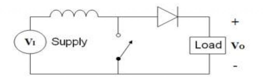
What is the Boost convertor?
A boost converter, or a “step-up” converter, does the opposite of the buck converter. It produces a larger output voltage than the input voltage. The difference from the buck converter is that the inductor is placed on the same side as the power supply of the switch. As a result, the power supply stores energy in the inductor when the switch is ON. However, the boost converter does not supply any energy to the load in the ON state, which results in a voltage over the inductor of VL = VI . When the switch alters, the energy in the inductor tends to collapse and the polarity changes. This results in that the energy in the inductor is added to the supplied energy, giving it a boost and hence produces a larger output than the input. The energy of the inductor is given by Equation.
D=Vl/V0
The output voltage is determined by the changes in the inductor current, which depends on the time periods in ON or OFF states. The change in inductor current is shown in Appendix A and from these equations the duty cycle of the converter can be determined. The duty cycle of a boost
converter is given by:
D=1-Vl/V0
A boost converter is used in the battery charger to “boost” the voltage produced by the solar cells to the proper battery voltage. When operating with voltage converters it is important to consider the Ohm’s law of power, P = VI. Since the power is equal on both sides of the converter, Ohm’s law presents that the current changes when the voltage changes to maintain the power. It is therefore important not to make large conversions when the current is a factor in the system. Hence, a major increase in the voltage will result in a major decrease of the current.
What is Cuk Regulator?
The Ćuk converter (pronounced Chook; sometimes incorrectly spelled Cuk, Cuk or Cuk) is a type of DC/DC converter that has an output voltage magnitude that is either greater than or less than the input voltage magnitude. It is essentially a boost converter followed by a buck converter with a capacitor to couple the energy. The non-isolated Cuk converter can only have opposite polarity between input and output. It uses a capacitor as its main energy-storage component, unlike most other types of converters which use an inductor. It is named after Slobodan Cuk of the California Institute of Technology, who first presented the design.
There are variations on the basic Cuk converter. For example, the coils may share single magnetic core, which drops the output ripple, and adds efficiency. Because the power transfer flows continuously via the capacitor, this type of switcher has minimized EMI radiation. The Ćuk converter allows energy to flow bi directionally by using a diode and a switch.
what is pulse width modulation PWM?
A Pulse Width Modulation (PWM) Signal is a method for generating an analog signal using a digital source. A PWM signal consists of two main components that define its behavior: a duty cycle and a frequency. The duty cycle describes the amount of time the signal is in a high (on) state as a percentage of the total time of it takes to complete one cycle. The frequency determines how fast the PWM completes a cycle (i.e. 1000 Hz would be 1000 cycles per second), and therefore how fast it switches between high and low states. By cycling a digital signal off and on at a fast enough rate, and with a certain duty cycle, the output will appear to behave like a constant voltage analog signal when providing power to devices. Example: To create a 3V signal given a digital source that can be either high (on) at 5V or low (off) at 0V, you can use PWM with a duty cycle of 60% which outputs 5V 60% of the time. If the digital signal is cycled fast enough, then the voltage seen at the output appears to be the average voltage. If the digital low is 0V (which is usually the case) then the average voltage can be calculated by taking the digital high voltage multiplied by the duty cycle, or 5V x 0.6 = 3V. Selecting a duty cycle of 80% would yield 4V, 20% would yield 1V, and so on. PWM signals are used for a wide variety of control applications. Their main use is for controlling DC motors but it can also be used to control valves, pumps, hydraulics, and other mechanical parts. The frequency that the PWM signal needs to be set at will be dependent on the application and the response time of the system that is being powered. Below are a few
applications and some typical minimum PWM frequencies required:
- Heating elements or systems with slow response times: 10-100 Hz or higher.
- DC electric motors: 5-10 kHz or higher
- Power supplies or audio amplifiers: 20-200 kHz or higher
Note: Certain systems may need faster frequencies than what is listed here depending on the type
of response desired.
Below are some graphs demonstrating PWM signals with different duty cycles.
Also read here