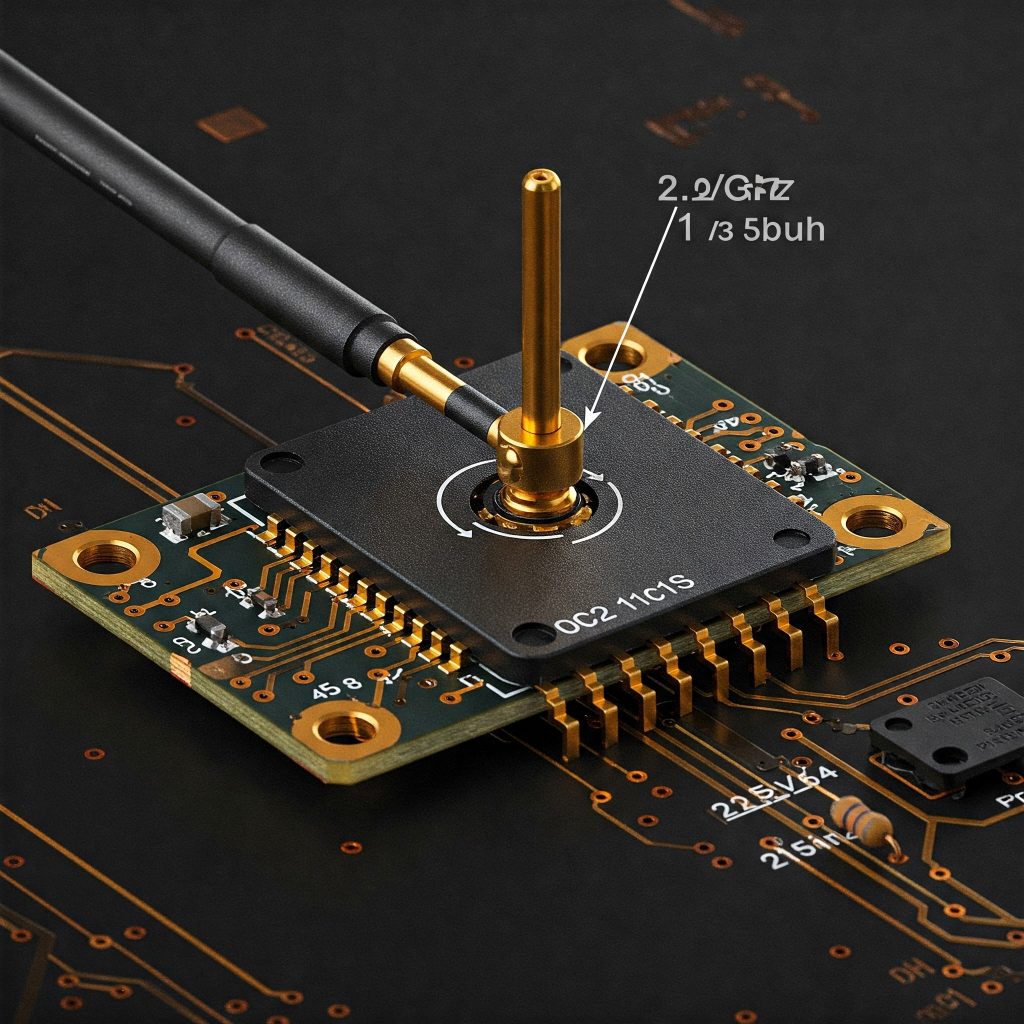
Developing a 2.4 GHz embedded product with a router PCB board is quite challenging and involves multiple things to be kept in mind. It involves multiple steps including component selection, schematic design, PCB layout, firmware development and finally testing.
But before that you need to understand the basics.
- 4 GHz WiFi: This refers to the wireless communication standard operating in the 2.4 GHz frequency band. It’s widely used for home and office networks due to its longer range and ability to penetrate walls.
- Embedded Product Development: This involves designing electronic systems that are integrated into larger products, such as home appliances, industrial equipment, or IoT devices.
- Router PCB: A printed circuit board (PCB) is the physical foundation of a router, holding all the electronic components and providing the necessary connections.
Advantages of 2.4 GHz PCB Antenna
The small size of a 2.4 GHz PCB antenna is one of its primary benefits. The antenna requires very little room and is easily fitted into compact devices because it is integrated onto the PCB. Its affordability is an additional benefit. A cost-effective option for wireless communication equipment, PCB antennas may be made in large quantities and are reasonably priced to build.
A 2.4 GHz PCB antenna is not only inexpensive and tiny, but it may also perform well. The wireless communication device’s signal strength and range can be enhanced by designing the antenna to have a certain radiation pattern and gain. You can say that it is cost effective solution for wireless communication devices.

Key Considerations for your 2.4 GHz WiFi Router PCB
Here are the key considerations for your 2.4 GHz WiFi router PCB:
1. Define Requirements:
- Functionality: Find out what functions your router has (e.g., Ethernet connections, USB, WiFi 2.4 GHz, etc.).
- Performance: Specify the number of connected devices, data rates, and range.
- Power Supply: Choose the power usage and input voltages (5V, 12V, etc.).
- Regulatory Compliance: Verify that WiFi devices adhere to FCC, CE, or other regional standards.
2. Selection of Components:
- WiFi Module: Based on your unique needs (such as range, data rate, and power consumption), select an appropriate 2.4 GHz WiFi module. ESP32, ESP8266, and other modules with integrated antennae are popular choices.
- Processor: Pick a microcontroller or processor capable of managing network address translation (NAT) and packet forwarding, among other routing functions.
- Memory: Find out how much RAM and flash memory are needed for the network data and firmware.
- Ethernet PHY: Select an appropriate PHY chip if you require an Ethernet port.
- Other Components: Take into account extra parts such as reset circuits, crystal oscillators, and power regulators.
3. PCB Layout:
- Ground Plane: A solid ground plane is crucial for RF performance and noise reduction.
- Power Traces: Keep power traces wide and short to minimize voltage drops and noise.
- RF Traces: Use short, direct traces for the WiFi module’s RF connections to minimize signal loss. (Keep high-speed signals (e.g., WiFi RF traces) short and impedance-controlled (typically 50 ohms). Avoid sharp bends in RF traces.)
- Use ground planes to reduce EMI.
- Component Placement: Place heat-sensitive components away from each other and provide adequate thermal relief.
- Antenna Considerations: If using an external antenna, ensure proper grounding and a clear path for signal transmission.
4. RF Trace Design
- Impedance match the antenna trace to 50Ω.
- Use microstrip or coplanar waveguide with proper calculations (e.g., KiCad’s Saturn PCB Toolkit).
- Create the schematic by connecting the WiFi module, microcontroller, memory, Ethernet PHY, and other peripherals.
- Add decoupling capacitors, resistors, and other passive components as needed.
- Ensure proper grounding and power distribution.
5. Firmware Development
- Develop firmware for the microcontroller to handle WiFi connectivity, routing, and other features.
- Use SDKs provided by the WiFi module/IC manufacturer.
- Implement protocols like TCP/IP, DHCP, and DNS.
6. Firmware Structure:
- Wi-Fi Stack: ESP-IDF (for ESP32) or OpenWrt (for MT7628).
- Network Protocols: DHCP, TCP/IP, NAT, and firewall configurations.
- Web Interface: Configuration through a web-based UI (HTML/JS with HTTP server).
- Security: WPA2/WPA3 support, firewall rules, and encrypted communications.
Prototype and Test: Order a prototype PCB and assemble it. Test the functionality of the router, including WiFi connectivity, routing performance, and network management features.
Always consult the datasheets of the components you are using for detailed specifications and design guidelines. Consider using electromagnetic simulation tools to optimize the PCB layout and antenna design. Also, if your router is expected to operate in a high-temperature environment, implement thermal management techniques, such as heat sinks or fans.
By following these steps and paying attention to the key considerations, you can successfully design a 2.4 GHz WiFi router PCB for your embedded product.
Tools and Resources
FS Circuits: For expert PCB assembly, manufacturing, and designing help.
- PCB Design Tools: KiCad (free), Altium Designer, Eagle.
- Simulation Tools: Ansys HFSS, CST Studio Suite (for RF simulation).
- Development Boards: Use evaluation boards for your WiFi module to prototype quickly.
Example Components
- WiFi Module: ESP32-WROOM-32 (2.4 GHz WiFi + Bluetooth).
- Microcontroller: STM32F4 series (ARM Cortex-M4).
- Ethernet PHY: LAN8720A.
- Antenna: PCB trace antenna or external antenna like a ceramic chip antenna.