Table of Contents
Introduction to comparator
How to design voltage comparator with op-amp? Design of voltage comparator with op-amp is very simple. There are two approaches for designing a comparator: zero level detector and non-zero level detector. A comparator is a specific operation amp circuit that looks at two information voltages and produces a yield that is consistently at both of two states, showing the more prominent or not exactly connection between the information sources. Comparators give exceptionally quick exchanging times, and numerous have extra abilities, (for example, quick engendering delay or inside reference voltages) to streamline the examination work. For instance, some super fast comparators can have engendering postponements of as meager as 500 ps. Since the yield is consistently in one of two states, comparators are regularly used to interface between a simple and computerized circuit. For less basic applications, an operation amp running without negative input (open-circle) is regularly utilized as a comparator. In spite of the fact that operation amps are much increasingly slow other exceptional highlights, they have high open-circle acquire, which empowers them to distinguish minuscule contrasts in the sources of info. All in all, comparators can’t be utilized as operation amps, yet operation amps can be utilized as comparators in noncritical applications. Since an operation amp without negative criticism is basically a comparator, we will take a gander at the correlation work utilizing a ordinary operation amp.
design of voltage comparator with op-amp
There are two approaches for designing the comparator circuit with op-amp
- Zero level detector
- Non-zero level detector
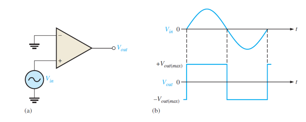
design of voltage comparator with op-amp for Zero-Level Detection
One utilization of an operation amp utilized as a comparator is to decide when an information voltage surpasses a specific level. Figure below shows a zero-level locator. Notice that the transforming input(-) is grounded to deliver a zero level and that the information signal voltage is applied to the noninverting input (+) . As a result of the high open-circle voltage acquire, a very little distinction voltage between the two information sources drives the intensifier into immersion, causing the yield voltage to go as far as possible. For instance, consider an operation amp having Aol =100,000. A voltage contrast of just 0.25 mV between the data sources could create a yield voltage of (0.25 mV)(100,000) = 25 V if the operation amp were skilled. Be that as it may, since most operation amps have greatest yield voltage constraints close to the estimation of their dc supply voltages, the gadget would be crashed into immersion. Below Figure (b) shows the consequence of a sinusoidal info voltage applied to the noninverting contribution of the zero-level finder. At the point when the sine wave is positive, the yield is at its most extreme positive level. At the point when the sine wave crosses 0, the speaker is headed to its inverse state and the yield goes to its greatest negative level, as appeared. As should be obvious, the zero level locator can be utilized as a squaring circuit to deliver a square wave from a sine wave.
design of voltage comparator with op-amp Non-Zero-Level Detection
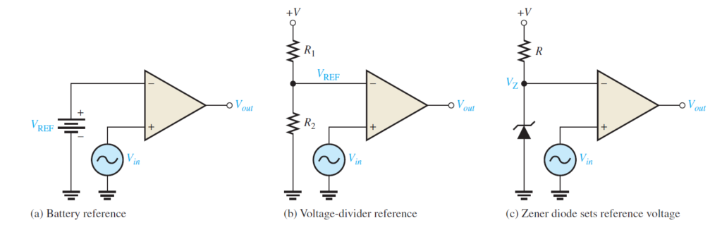
The zero-level identifier in Figure below can be altered to distinguish positive and negative voltages by interfacing a fixed reference voltage source to the reversing contribution, as appeared in following figure . A more functional course of action is appeared in Below Figure (b) utilizing a voltage divider to set the reference voltage, VREF, as follows:
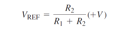
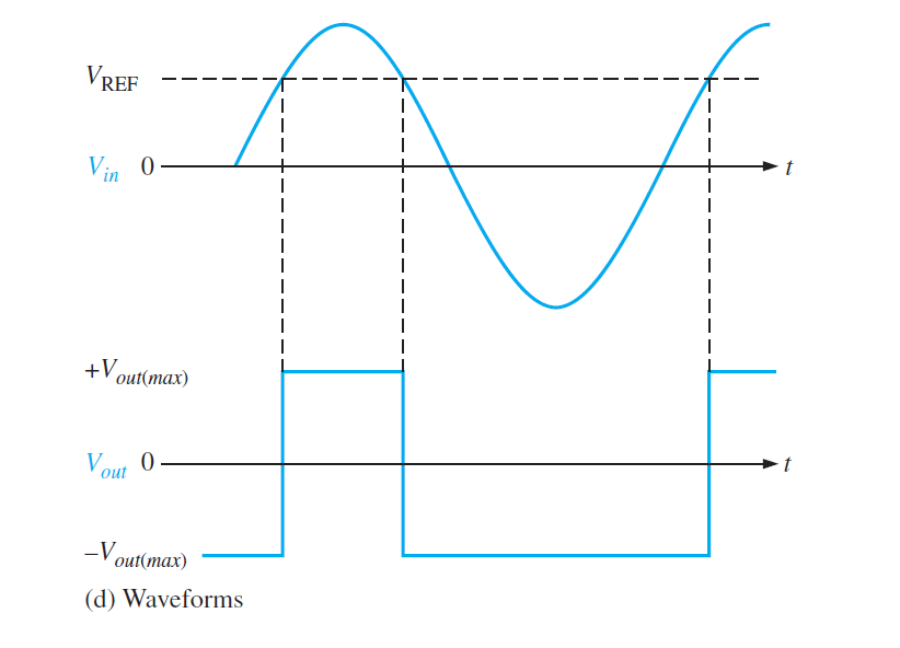
where +V represents the positive dc supply voltages value. While in figure (c) Zener diode is used to set the reference voltages. As long as input voltages are less than the reference voltages, yield stays at the most extreme negative level.
At the point when the info voltage surpasses the reference voltage, the yield goes to its most extreme positive voltage, as appeared in Figure below with a sinusoidal information voltage.
Effects of Input Noise on Comparator Operation
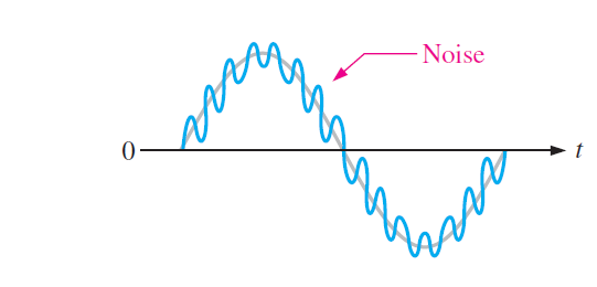
In numerous reasonable circumstances, commotion (undesirable voltage changes) shows up on the info line. This clamor voltage gets superimposed on the information voltage, as appeared in Figure below for the instance of a sine wave, and can cause a comparator to unpredictably switch yield states.
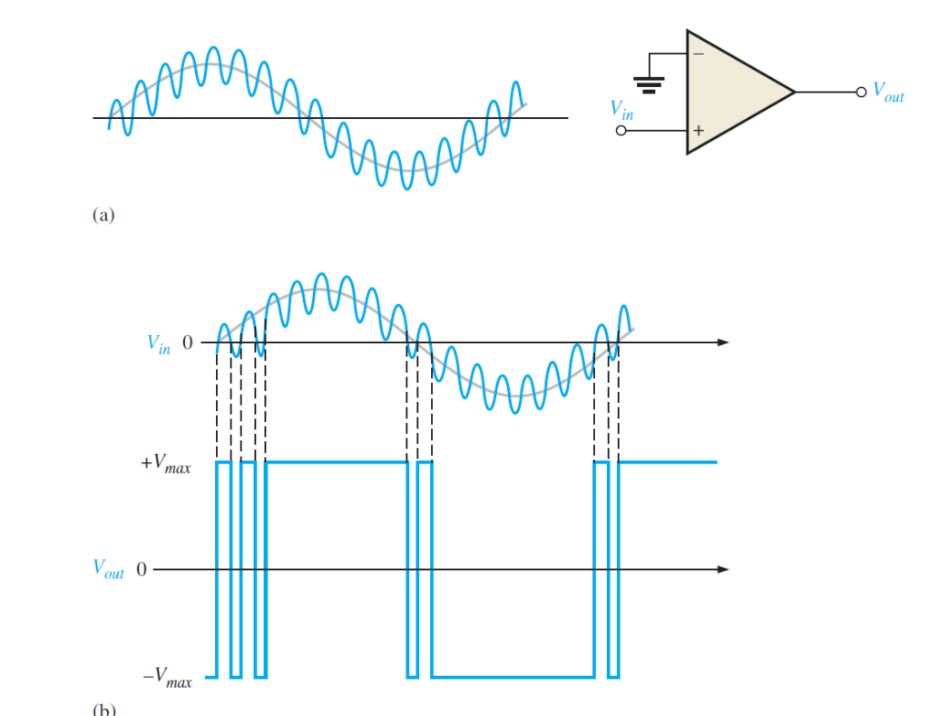
To comprehend the likely impacts of clamor voltage, think about a low-recurrence sinusoidal voltage applied to the noninverting (-) contribution of an operation amp comparator utilized as a zero-level indicator, as appeared in below Figure (a). Part (b) of the figure shows the info sine wave in addition to commotion and the subsequent yield. At the point when the sine wave approaches 0, the vacillations because of commotion may cause the absolute contribution to differ above and under 0 a few times, subsequently creating a flighty yield voltage.
Also read here:
What are the basics of operational amplifier? Why do we use operational amplifier (op-amp) ?
2 thoughts on “How to design voltage comparator using op-amp?”