Table of Contents
Define a Capacitor
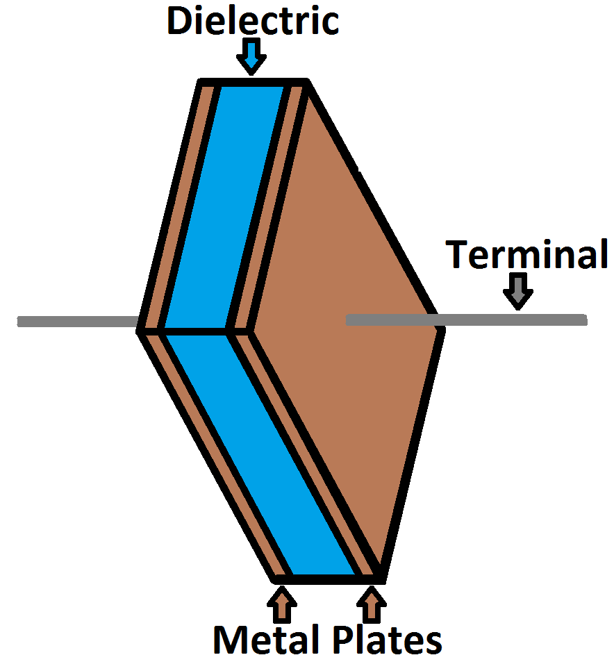
What are the Components of a Capacitor? A capacitor is an electrical device used mainly for the storage of charge. Basically it stores energy in the form of electric charge. It is connected with two terminals. Also adding in the information of capacitor, that it is a passive electrical circuit element.
Unit of a Capacitor
The function of a capacitor is called capacitance. It is defined as the ability of a capacitor to store electrical charge. There always exists some natural capacitance between two electrical conductors in a circuit. A capacitor is deigned in such a way that it adds in the value of already present capacitance. Initially, the capacitor was referred to as a condenser or condensator. These names are still in use today in other languages but in English language this word is used only with condenser microphone, also called capacitor microphone.
Composition of a Capacitor
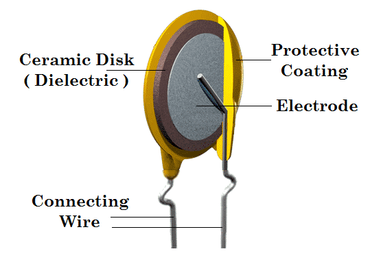
Many types of capacitors are widely in use now a day. However, their construction is mainly based on their working. A typical capacitor contains at least two electrical conductor plates separated by a small distance and sometimes the gap is filled with some type of dielectric. The conductor can be a film, a foil or an electrolyte ready to conduct charge. While the dielectric being insulating in nature, increases the charge storing capacity of a capacitor. Some common oxide layers used as dielectrics in capacitors are
- Glass
- Ceramic
- Film
- Paper
- Mica
- Air
In 1740s, the simplest form of capacitors was used by Europeans. These capacitors were water-filled glass jars that could store electric charge. These glass jars were called Leyden jars. Today the influence of capacitor in a circuit cannot be ignored. They block direct current while allowing alternating current to pass. Similarly, they smooth the output of power supplies and are also used in radios for tuning frequencies. They have many uses in daily life that after resistor, they become the most common circuitry element.
How Capacitor Works?
The flow of electric charges across a circuit is called electric current. This electric current is required by every component of the circuit to perform its function. When this current flows into the capacitor, the charges get separated. Negative charges get lined up at one plate of the capacitors. These negative charges being great in number and density repels the other negative charges. As a result of which, positive charges line up and the other plate becomes positively charged.
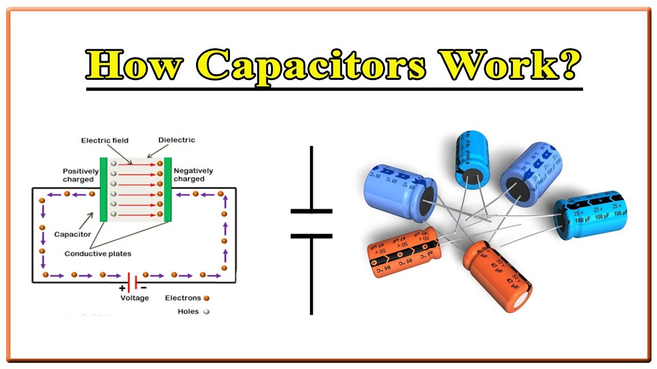
These positive and negative charges according to their nature attract each other. But due to the presence of dielectric they cannot come close to each other. The charges thus remain on their plates until they have somewhere else to go. The stationary charges on these plates create an electric field, which induces electric potential energy and voltage. Also check the properties of a capacitor here.
Charging and Discharging of a Capacitor
At the point when positive and negative charges combine on the capacitor plates, the capacitor becomes charged. A capacitor can hold its electric field, hold its charge, on the grounds that the positive and negative charges on every one of the plates draw in one another yet never arrive at one another.
Eventually the capacitor plates will be so bursting with charges that they can’t hold any longer. There are an adequate number of negative charges on one plate that they can repulse any others that attempt to join. This is where the capacitance (farads) of a capacitor becomes an integral factor, which lets you know the most extreme measure of charge the capacitor can store.
If a path is created in the circuit that allows the charges to find another path to each other, they will leave.
How to Calculate Charge, Current and Voltage of a Capacitor?
The capacitance of a capacitor, or how many farads it has, indicates how much charge it can store. The potential difference (voltage) between the plates of a capacitor determines how much charge it is currently storing. This equation can be used to model the charge, capacitance, and voltage relationship:
A capacitor’s capacitance should always be a constant and well-known value. As a result, we can change the voltage to increase or decrease the charge of the capacitor. More voltage equals more charge, while lower voltage equals less charge.
That equation also allows us to define the value of one farad.
One farad (F) is the capacity of one volt to store one unit of energy (coulombs). It is represented by symbol (F). other smaller units such as micro, pico and nano are commonly used with it.
Relation Between Current and Voltage of a Capacitor
Given that current is the rate at which charge flows, we can extend the charge/voltage/capacitance equation in order to determine how capacitance and voltage affect current. The basic relationship between a capacitor and voltage and current is as follows: the amount of current flowing through a capacitor is determined by both capacitance and the rate at which the voltage rises or falls. A large positive current is induced through a capacitor if the voltage across it rapidly rises. A slower rise in voltage across a capacitor results in a lower current flowing through it. If the voltage across a capacitor is constant and unchanging, no current will flow through it. The relationship is given by
I(t) = dQ(t) / dt = C dV(t) / dt
Or it can be expressed in the integral form for current that is
$$
V(t)=\frac{Q(t)}{C}=V\left(t_0\right)+\frac{1}{C} \int_{t_0}^t I(t) d T
$$
The derivative of voltage shows how fast the voltage is changing according to time. If voltage is steady, it means there is no change in voltage. Thus the derivative will be equal to zero and the current will also be zero. That’s why current cannot flow through a capacitor having a steady DC voltage.
What are the Operational Capacitors?
Circuit Equivalence According to Time Limit
Capacitor show strange and variable behavior at different time instants. It is explained below how a capacitor does that.
- In the long-time limit, after charging/discharging no current flows across the capacitor. This happens because the circuit has been made saturated. Thus an open circuit behavior is observed in this case.
- In the short-time limit, if the capacitor starts charging with a certain voltage, we can replace the voltage with an ideal voltage source since the potential difference across capacitor is determined. For discharged capacitor, short-time limit refers to a short circuit in the circuitry network.
Parallel-Plate Capacitor
A capacitor that consists of two plates parallel to each other and separated by a distance filled with a dielectric, is commonly referred to as parallel-plate capacitor. It is assumed that the gap between the plates of the capacitor is much smaller than the actual area of the plates. The separation between the plates is uniform over the plate area. Thus the electric field between the plates is also uniform. Resulting in constant values of electric field is and causing it to move in direction perpendicularly to the plate surface. Thus a direct relation between area and electric field of a capacitor can be observed.
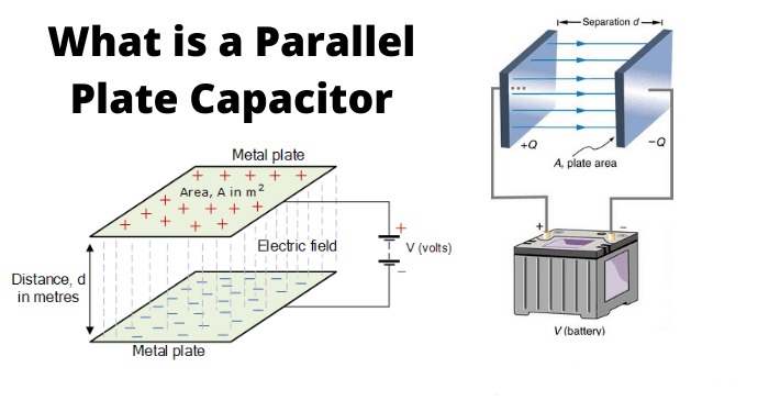
If a charge of +Q is present at one plate of the capacitor and –Q is present on the other plate of the capacitor, then due to uniform charge density, this charge will spread evenly all across the surface of the capacitor plates. The charge density can then be σ=±Q/A. Its units can be determined easily that are coulombs per square meter. From Gauss’s law the magnitude of the electric field between plates is given as E=σ/ε. The potential difference between the plates of the capacitor is defined as the line integral of electric field over a line from one plate to another.
$$
V=\int_0^d E(z) d z=E d=\frac{\sigma}{\varepsilon} d=\frac{Q d}{\varepsilon A}
$$
The capacitance is defined as $\mathrm{C}=\mathrm{Q} / \mathrm{V}$. substituting $\mathrm{V}$ in above equation
$$
C=\frac{\varepsilon A}{d}
$$
Thus in a capacitor to achieve maximum capacitance, a high permittivity dielectric material, larger area of plates and small separation between the plates is required.
Interleaved Capacitor
For n number plates in a capacitor, the total capacitance is given by following formula
$$
C=\varepsilon_0 \frac{A}{d}(n-1)
$$
Where
$$
C=\frac{\varepsilon A}{d}
$$
is the capacitance for a single plate capacitor. Every pair of adjacent plates acts as a separate capacitor; hence the number of pairs is always one less than the number of plates present.
Energy Stored in a Capacitor
Work is done on a capacitor by an external source. The charge and voltage on a capacitor increases in their magnitude. This happens due to the work done in moving a charge from negative to positive plate of the capacitor against the opposing electric field generated by the capacitor. The total energy stored in a capacitor is equal to the total work done in establishing this electric field between the plates from an uncharged state.
$$
W=\int_0^Q V(q) d q=\int_0^Q \frac{q}{C} d q=\frac{Q^2}{2 C}=\frac{1}{2} V Q=\frac{1}{2} C V^2
$$
Where Q is the stored charge, V is the potential difference across the capacitor and C is the capacitance. The voltage will be present in the capacitor until the charge is removed.
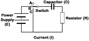
DC Circuit Containing a Capacitor
Here we will discuss the simple dc circuit that consists of a resistor, a capacitor a switch and a constant DC source. It is basically called a charging circuit for a capacitor. When switch is open and the capacitor is uncharged nothing happens. But when at t=0, the switch is closed then capacitor starts charging. According to Kirchhoff’s voltage law
$$
V_0=V_{\text {RESISTOR }}(t)+V_{\text {CAPACITOR }}(t)=\mathrm{i}(\mathrm{t}) \mathrm{R}+\frac{1}{C} \int_{t_0}^t i(t) d t
$$
After differentiation and multiplication by C, we get a first-order differential equation
$$
R C \frac{d i(t)}{d t}+i(t)=0
$$
At $\mathrm{t}=0$, capacitive voltage is zero and resistive voltage is $\rfloor(0)=\mathbf{V}_0 / \mathrm{R}$. now solving the differential equations
$$
\begin{gathered}
I(t)=\frac{V_0}{R} e^{-t / T \theta} \\
V(t)=V_0\left(1-e^{-\frac{t}{T \theta}}\right) \\
Q(t)=C V_0\left(1-e^{-\frac{t}{T \theta}}\right)
\end{gathered}
$$
As $\mathrm{t}_0=\mathrm{RC}$ is the time constant of the capacitive system. When the capacitor reaches equilibrium with source voltage, the voltage and the current in the circuit decay drastically. In case of discharging capacitor, the capacitor’s initial voltage $\left(V_G\right)$ is replaced $V_0$.
$$
\begin{array}{r}
I(t)=\frac{V_{C i}}{R} e^{-\frac{t}{T \theta}} \\
V(t)=V_{C i} e^{-\frac{t}{T \theta}} \\
Q(t)=C V_{C i} e^{-\frac{t}{T \theta}}
\end{array}
$$
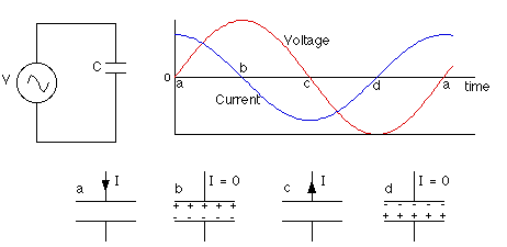
AC Circuit Containing a Capacitor
When a circuit containing capacitor is power by an ac source then the formulation of results is quite different. In AC we talk about impedance which is collectively the sum of reactance and resistance. It describes the phase difference between current and voltage at any given frequency. The reactance and impedance of a capacitor are given as
$$
\begin{gathered}
X=-\frac{1}{\omega C}=-\frac{1}{2 \pi f C} \\
Z=\frac{1}{j \omega C}=-\frac{j}{\omega C}=-\frac{j}{2 \pi f C}
\end{gathered}
$$
Where $\mathrm{j}$ is frequency and $\omega$ is angular frequency of the signal. The $-\mathrm{j}$ phase indicates that AC voltage lags the AC current by $90^{\circ}$.
A capacitor connected to a voltage source in the form of sine waves, causes a minor current to flow. The voltage is then taken as $\mathrm{Y}_0 \cos (\omega t)$. And the current is expressed as
$$
I=C \frac{d V}{d t}=-\omega C V_0 \sin (\omega t)
$$
At $\sin (\omega t)=-1$, the capacitor has a maximum value for current. The ratio of peak voltage to peak current or which we can commonly refer to as capacitive reactance is given as
$$
X_C=\frac{V_0}{I_0}=\frac{V_0}{\omega C V_0}=\frac{1}{\omega C}
$$
The capacitive current can be expressed in the forms of cosine so that it would be easy to compare it with source voltage
$$
I=-I_0 \sin (\omega t)=I_0 \cos (\omega t+90)
$$
Capacitor Connected in Series and Parallel
Now we will discuss how the analysis of a capacitive circuit should be done if more than one capacitors are connected either in series or in parallel combinations.
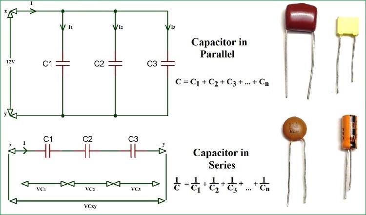
Parallel Connection of a Capacitor
In parallel combinational circuit, the voltage across each capacitor remains same. The current varies. The individual capacitances add up to form the equivalent capacitance.
$$
C_{E Q}=\sum_i C_i=C_1+C_2+\cdots+C_N
$$
Series Connection of a Capacitor
The current in the series remains the same whereas the voltage changes. As voltage is continuously changing for each capacitor connected in series the relative charge on each plate of the capacitor the individual capacitances.
$$
\frac{1}{C_{E Q}}=\sum_i \frac{1}{C_i}=\frac{1}{C_1}+\frac{1}{C_2}+\frac{1}{C_3}+\cdots+\frac{1}{C_N}
$$
Non-Ideal Behavior of a Capacitor
Sometime real capacitors deviate from their idealism. There are a number of ways of this deviation. Some ways can be dealt easily by just adding some multiples but in other cases this cannot be done. These special cases should be dealt separately.
1) BREAKDOWN VOLTAGE
Breakdown voltage is a point in voltage where the dielectric material due to exposition of voltage, becomes conductive in nature. This voltage is given by the product of the dielectric strength and the distance of separation between conductor plates
$$
V_{\boldsymbol{b} \boldsymbol{d}}=\boldsymbol{E}_{\boldsymbol{d} s} \boldsymbol{d}
$$
Breakdown voltage also indicates the maximum amount of energy that a capacitor can store. As capacitance and breakdown voltages both are scaled according to dielectric thickness, all capacitors made with a specific dielectric have almost the same breakdown voltage. This breakdown voltage is greatly influenced by the geometry of capacitors.
The general breakdown procedure is that the field strength becomes large enough. Thus it becomes difficult to pull the electrons in the dielectric from their atoms which results in conduction. Other factors that contribute to this process are impurities in the dielectric, pressure, humidity and temperature.
What is the Q Factor?
Q factor or quality factor as the name suggests, is the measure of efficiency of a capacitor at a given frequency. It is the ratio of reactance to the resistance. The higher the Q factor, the more the behavior of capacitor is close to idealism.
$$
Q=\frac{X_C}{R}=\frac{1}{\omega C R}
$$
Where $\omega$ is the angular frequency, $\mathrm{C}$ is the capacitance, $\mathrm{X}_{\mathrm{c}}$ is the capacitance reactance and $R$ is the equivalent series resistance of the capacitor.
APPLICATIONS OF CAPACITORS
Some common applications of capacitors are listed below
ENERGY STORAGE: a capacitor stores energy when disconnected from its charging circuit, so it is used like a temporary batter or rechargeable battery.
DIGITAL MEMORY: a capacitor is used to construct dynamic digital memory for computers.
– PULSED POWER AND WEAPONS: capacitors are widely used in weapons and bombings
– POWER CONDITIONING: capacitors are used for smoothing signals and conditioning powerful signals
– SUPPRESSION AND COUPLING
– MOTOR STARTERS
– SIGNAL PROCESSING
– SENSING
$>$ OSCILLATORS
> PRODUCING LIGHT (light emitting capacitor)
Also read here: