How to control the direction of DC motor with PIC ?
How to control the direction of DC motor with PIC ? PIC is a family of microcontrollers made by Microchip Technology, gotten from the PIC1650 originally developed by General Instrument’s Microelectronics Division. The name PIC at first referred to Peripheral Interface Controller, and is presently expanded as Programmable Intelligent Computer.
PIC microcontrollers ( Programmable Interface Controllers), are those electronic circuits that can be programmed to carry out immense range of tasks. They can be modified to be timers or to control a production line and substantially more.
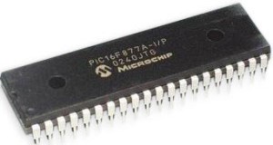
PIC microcontrollers are steady and defective of PIC rate is less. The performance of the PIC microcontroller is quick a direct result of utilizing RISC design. When contrasting with other microcontrollers, power utilization is exceptionally less and writing computer programs is additionally simple.
DC Motor:
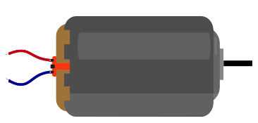
An electric motor worked by DC (direct current) is known as a DC motor (not at all like an acceptance engine that works by means of a rotating flow). A DC motor converts DC electrical energy into mechanical energy.
A DC motor is a mix of a stator which contains fixed magnets and an armature which is an iron center with protected wire twisted around it. The strength of magnetic field created in the framework is dictated by the measure of current shipped off the curl, number of windings and nature of the material of the loop. In some DC machines, the stator utilizes electromagnets to improve power over the motor. The approach of force hardware has helped DC motors to improve its capacities by keeping a powerful lower voltage.
Principle of DC Motor:
At the point when a current-conveying conductor is set in an magnetic field, it encounters a force and tends to move. As such, when a magnetic field and an electric field associate, a mechanical power is created. The DC motor or direct current motor deals with that rule. This is known as motoring action.
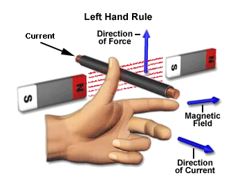
The direction of rotation of this motor is given by Fleming’s left hand rule, which expresses that if the forefinger, center finger, and thumb of your left hand are stretched out commonly opposite to one another and if the pointer addresses the course of the attractive field, center finger demonstrates the heading of the current, at that point the thumb addresses the course where power is capable by the shaft of the DC engine.
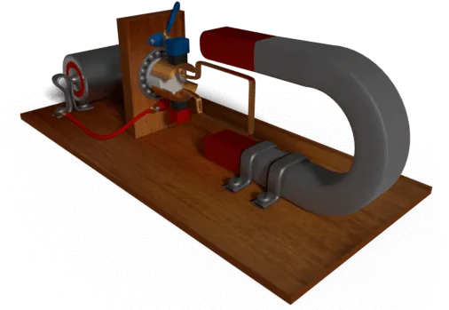
Basically and development insightful DC current motor is actually like a DC generator, yet electrically it is the exact inverse.
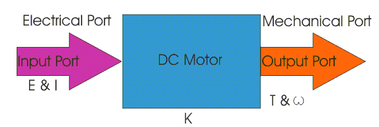
Here we dissimilar to a generator we supply electrical energy to the input port and get mechanical energy from the output port. In the DC motor over, the supply voltage E and flow I is given to the electrical port or the info port and we determine the mechanical output for example force T and speed ω from the mechanical port or yield port.
Parameter K relates the input and output port variables of the direct current motor.
So from the picture above, we can well understand that the motor is just the opposite phenomena of a DC generator, and we can derive both motoring and generating operation from the same machine by simply reversing the ports.
How to control the direction of DC motor with PIC ?
As the name infers DC motors are electrical machines which work under DC power. It changes electrical energy over to mechanical energy. In light of a few of its benefits including the rapid control offices, DC motors were generally utilized in bunch applications. Progression in hardware has as of late caused a shift from DC engines to AC fueled engines. And, after its all said and done, the DC engines are liked in applications beginning from toys to electric vehicles. Here we discuss that how the direction of DC Motor can be controlled by using pic microcontroller.
We use H-bridge for this purpose: In order to solve the inability to rotate in both directions, H drive is useful. The name H bridge comes from structure of circuit because it resembles with letter H of English alphabets.
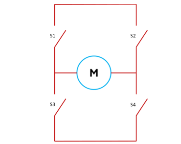
To rotate the engine, we need to close either S1 with S4 or S2 with S3. These will bring about the rotation in two ways. The following is a real circuit utilized for H bridge.
At the point when D is grounded and A is Vcc, transistors Q1 and Q4 will become ON and current goes through motor from left to right. To pass current from option to left, B ought to be grounded and terminal C in Vcc. This will bring about rotation of motor inverse way.
Driver ICs
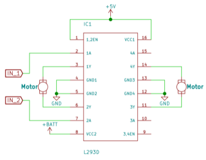
There are a few Motor driver chips and any current driver with adequate current output can be utilized for this reason. Yet, for utilizing it in the two ways, we need to utilize H-bridge driver IC like L293D. This IC can be utilized for turning one or the other way. A model circuit utilizing L293D is underneath:
Also read here