PIC18 Timer programming in assembly language
How to program timer in assembly language? PIC18 Timer programming in assembly language. There are 5 timers available in PIC18 series named as Timer0,Timer1, Timer2,Timer3, Timer4.
All these timers are 16 bits timers and they can be used for
- Introducing Time delays (For generating square waveforms.
- Event Counters
It depends on the clock source for what purpose these timers are programmed. If the internal clock source is used for providing the pulses, then it is used for introducing delays. If the clock pulses are provided from some external source on RA$ CLK0I, then it counts the events on each clock.
Timer0 registers
Here we will study only timer0 and timer0 is a 16-bit register comprised of TMR0H:TMR0L. Both these registers are 8-bits registers thus processing the 16-bit of data. These two registers can be used for storing the values like any special function registers and can be accessed easily. For example:
MOVWF TMR0H. So whatever the contents of WREG register are will be copied into the higher byte of timer0.
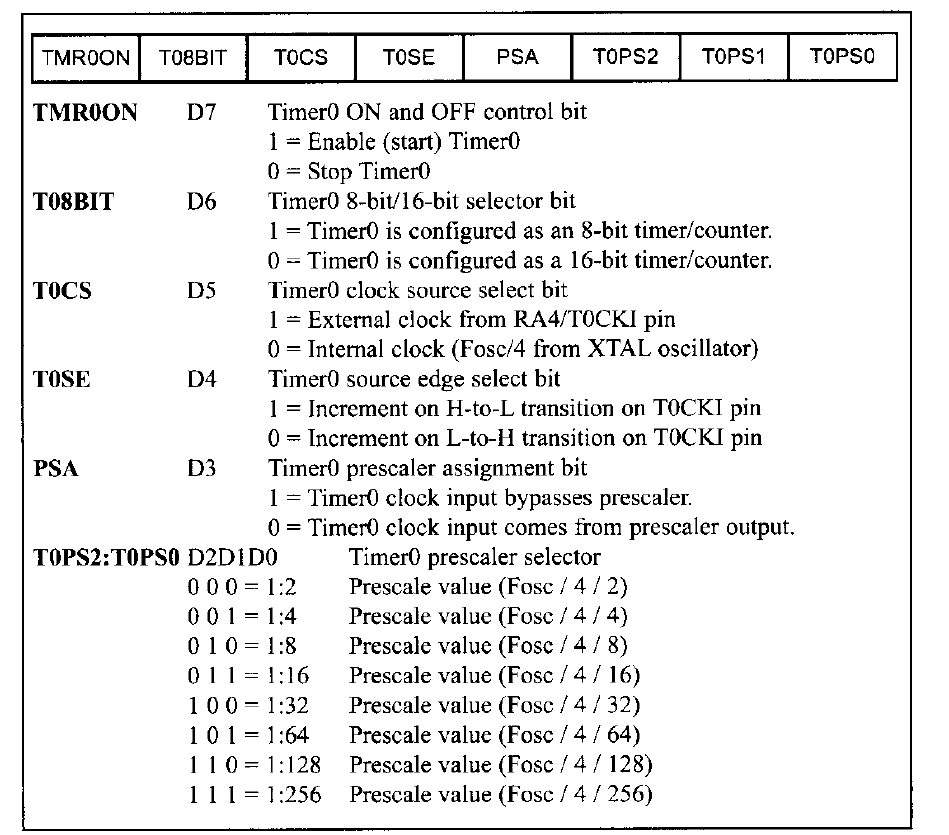
Configuration register for timer0.
By configuration we mean in which mode we will program the timer (8-bit or 16-bit), either the prescaler will be used or not, increment in timer value will be done from low to high or high to low pulse, when to switch ON or OFF the timer, internal or external clock source should be used.
How to monitor the timers of PIC18?
In order to keep monitoring either the timer has reached to its maximum value or not, we need to keep an eye on TMR0IF bit of interrupt control register. If we are using the 16-bit mode of timer, then when the timer reaches to its maximum value FFFFH, it rolls over from FFFFH to 0000H indicating the overflow. When it rolls over it also sets the TMR0IF bit to 1 indicating the timer has reached to its maximum value. How to program timer in assembly language?
16 bit TIMER0 programming of PIC18
Following are the steps that are used for programming the timer i, 16 bit mode.
- Set the mode of operation of Timer0 using TMR0CON register.
- Load both registers of TMR0 i.e., TMR0H and TMR0L byte. TMR0H must be loaded first. Since it is a 16-bit timer so you can load values from 0000H to FFFFH.
- After loading the resisters, start the timer using the command BSF T0CON, TMR0ON
- After starting the timer, it will start counting and will reach to its maximum value FFFFH. Once it rolls over it will set the bit TMR0IF. We need to stop the timer when it happens. This can be done using command BCF T0CON, TMR0ON.
- If we want to repeat the process, we need to reload the timers registers and keep repeating the steps again.
Watch here
Example
Write down a program for generating a square waveform with 50% duty cycle on PORTD.1. Timer0 is used for the time delay.
Solution
BCF TRISD,1
MOVLW 0X08
MOVWF T0CON
HERE1 MOVLW0XFF
MOVWF TMR0H
MOVLW 0XF1
MOVWF TMR0L
BCF INTCON,TMR0IF
BTG PORTD,1
BSF T0CON,TMR0ON
AGAIN1 BTFSS INTCON,TMR0IF
BRA AGAIN1
BCF T0CON,TMR0ON
BRA HERE1
Calculate the amount of delay introduced in the above example of PIC18 timer programming.
The value loaded in timer register is FFF1H which is equal to 65521.
Subtract it from 65536 always in 16-bit mode you will get 65536-65521= 15
If you are using crystal oscillator of 10MHz frequency then each clock period will be equal to 10Mhz/4=2.5MHz T=1/2.5Mhz=0.4usec.
So multiply 15 with 0.4usec=6usec.
Since this time is used either for the high or low part of a pulse. For a complete pulse multiply it with 2 =12usec.
and the frequency of the signal is 1/12usec=83Khz.
Also watch here
How to calculate the frequency of the signal generated using PIC18 microcontroller?
Also read here
How to import hex file into PIC microcontroller using PROTEUS