
Calculating the time Delays in PIC Programming
In this article I will explain how to calculate the time delays of delay routines in PIC microcontroller programming. Two factors that affect the delay size are: the oscillator frequency and the number of instructions involved in the delay routine.
Role of Crystal Oscillator:
The frequency of crystal oscillator helps to decide the size of a machine cycle. One machine cycle is actually equal to 4 clock periods. In other words, when clock periods of crystals are completed then we get a one machine cycle.
Machine Cycle
Machine cycle is the time required to execute a simple instruction. Almost all instructions in PIC take only one machine cycle. But there are some special instructions like BNZ, BC, BNC, BZ take 2 machine cycles.
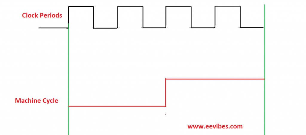
For this reason, we divide the crystal oscillator frequency by 4 first, and then we take the reciprocal of the resultant in order to measure the time delay of a single machine cycle.
Lets assume that the crystal oscillator frequency is 20MHz,
Fist divide it by 4 so : 20×106/4= 5×10⁶
Now take its reciprocal =200nSec.
So one machine cycle is of 200nSecs.
For getting the better idea, lets do an example.
Example for calculating the required delays in PIC18F4550
Write down a program to toggle the contents of PORTB after every 2 seconds when crystal frequency is 20MHz.
In this case
1 machine cycle= 200nSecs.
2Secs= 2,000,0000,000nSecs.
So,
2,000,0000,000nSecs=200nSecs.
2,000,0000,000/200=10,000,000
Let’s factorize it
250X250X160
As delay routine has 5 machine cycles so, we will further factorize it
250X250X32X5
Hence the counter values are:
250
250
And 32.
Code
#INCLUDE<P18F4550.INC>
R2 EQU 0X2
R3 EQU 0X3
R4 EQU 0X4
ORG 0
MOVLW 0X55
MOVWF PORTB
BACK CALL DELAY
COMF PORTB
GOTO BACK
DELAY MOVLW D’250′
MOVWF R4
BACK1 MOVLW D’250′
MOVWF R3
AGAIN MOVLW D’32’
MOVWF R2
HERE NOP
NOP
DECF R2,F
BNZ HERE
DECF R3,F
BNZ AGAIN
DECF R4,F
BNZ BACK1
RETURN
END
In order to check the exact time delay, we will open settings from the debugger tab on MPLAB software. After opening the settings, you will adjust the frequency which is 20MHz in our case. Then Open stopwatch from the debugger tab again. Initially you will see all its value are 0 (reset).
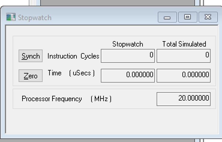
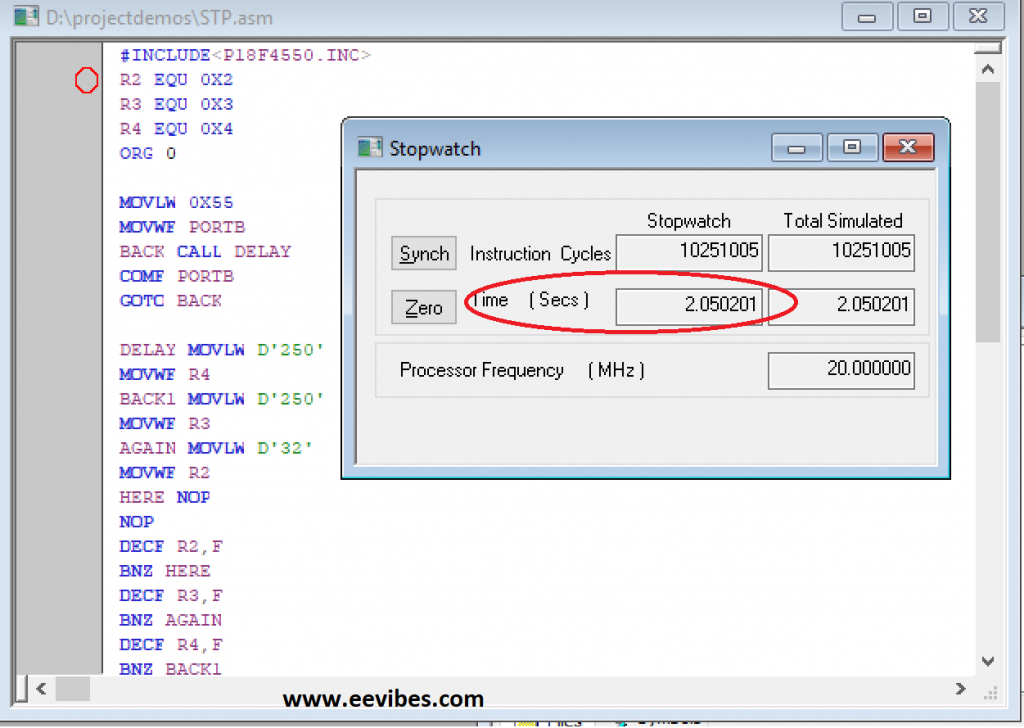
Then set the breakpoints of your code. The breakpoint in your code can be set by double clicking on the code line number as shown below.
You can set two breakpoints in order to get the exact delay. Once you have set the breakpoints just Run it once. This will give the time introduced by the delay routine in PIC.
The simulations results are shown below.
Now Lets do the reverse task and calculate the amount of delay introduced by the delay routine.
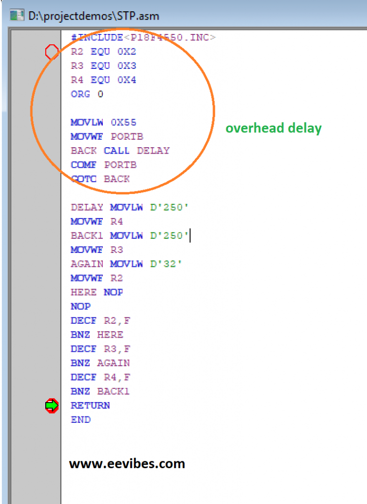
Here we will neglect the overhead delay. Overhead delay is because of the additional instructions outside the delay routine as circled in the figure below.
Instructions Machine Cycles
DELAY MOVLW D’250′ 1
MOVWF R4 1
BACK1 MOVLW D’250′ 1
MOVWF R3 1
AGAIN MOVLW D’32’ 1
MOVWF R2 1
HERE NOP 1
NOP 1
DECF R2,F 1
BNZ HERE 2
DECF R3,F 1
BNZ AGAIN 2
DECF R4,F 1
BNZ BACK1 2
RETURN 1
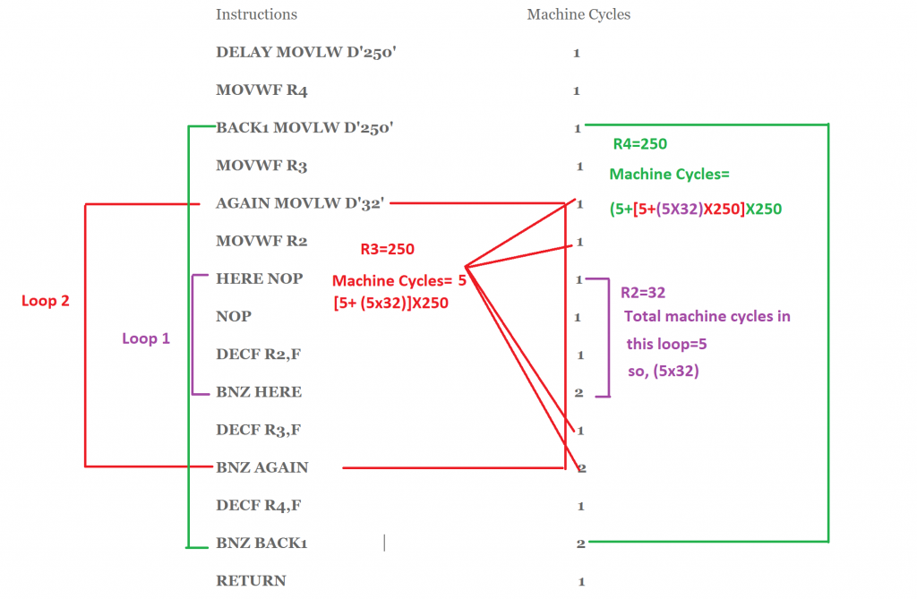
Now as we had assumed the oscillator frequency of 20 MHz so one machine cycle is of 200nSec duration.
= [([{(5X32)+5}X250]+5)X250]X200nSec

which is approximately equal to 2 Seconds.
Download Lab Manual 6
BCD and ASCII conversion in PIC microcontroller
Also read here
How to create a first project in PIC microcontroller using assembly language