Introduction
This article is about how to perform parallel printer interfacing with 8086/8088 microprocessor. In some applications, the microcomputer must synchronize the input or output of information to a peripheral device. Two examples of interfaces that may require a synchronized data transfer are a serial communications interface and a parallel printer interface.
Sometimes it is necessary as part of the I/O synchronization process first to poll an input from an I/O device and, after receiving the appropriate level at the poll input, to acknowledge this fact to the device with an output. This type of synchronization is achieved by implementing what is known as handshaking as part of the input/output interface.
Interfacing the Printer with Parallel Printer Port

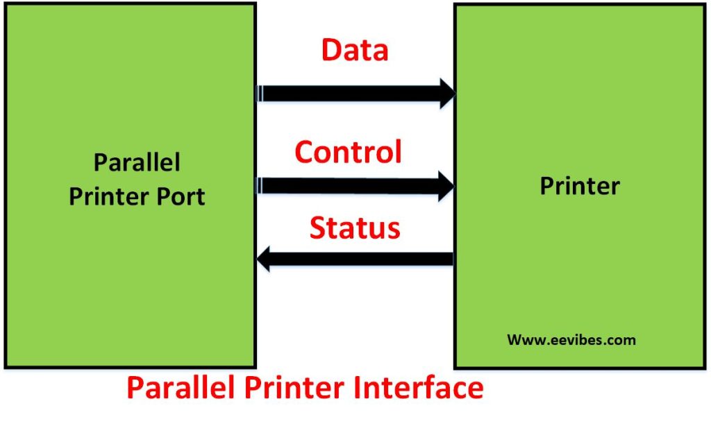
Figure above shows a conceptual view of the interface between the printer and a parallel printer port. There are three general types of signals at the printer interface:
- data,
- control,
- and status.
The data lines are the parallel path’s used to transfer data to the printer. Transfers of data over this bus are synchronized with an appropriate sequence of control signals. However, data transfers can only take place if the printer is ready to accept data.
Flowchart for Data Transfer for Parallel Printer Interface
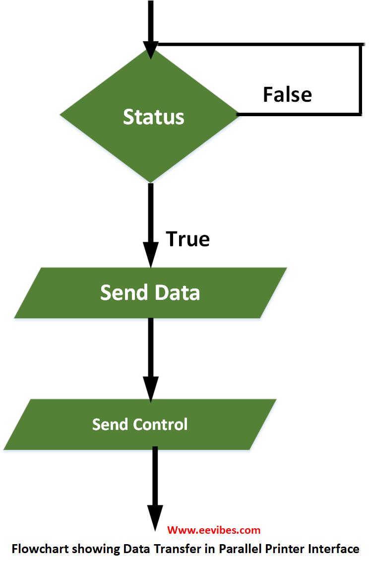
Printer readiness is indicated through the parallel interface by a set of signals called status lines. This interface handshake sequence is summarized by the flowchart shown in figure below.
The printer is attached to the microcomputer system at a connector known as the parallel printer port. On a PC, a 25-pin connector is used to attach the printer. Figure below shows the actual signals supplied at the pins of this connector. Note that there are five status signals available at the interface, and they are called Ack, Busy, Paper Empty, Select, and Error.
| Pin | Assignment |
| 1 | Strobe |
| 2 | DATA 0 |
| 3 | DATA 1 |
| 4 | DATA 2 |
| 5 | DATA 3 |
| 6 | DATA 4 |
| 7 | DATA 5 |
| 8 | DATA 6 |
| 9 | DATA 7 |
| 10 | Ack |
| 11 | Busy |
| 12 | Paper Empty |
| 13 | Select |
| 14 | Auto faxt |
| 15 | Error |
| 16 | Initialize |
| 17 | Slctin |
| 18 | Ground |
| 19 | Ground |
| 20 | Ground |
| 21 | Ground |
| 22 | Ground |
| 23 | Ground |
| 24 | Ground |
| 25 | Ground |
In a particular implementation only some of these signals may be used. For instance, to send a character to the printer, the software may test only the Busy signal. If it is inactive, it may be a sufficient indication to proceed with the transfer.
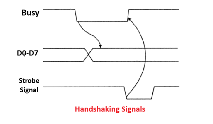
Following Figure shows a detailed block diagram of a simple parallel printer inter-face. Here we find eight data-output lines, Do through D7, control signal strobe (STB), and status signal busy (BUSY). The MPU outputs data representing the character to be printed through the parallel printer interface. Character data are latched at the outputs of the parallel interface and are carried to the data inputs of the printer over data lines Do through D7. The STB output of the parallel printer interface is used to signal the printer that new character data are available.
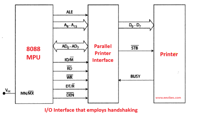
Whenever the printer is already busy printing a character, it signals this fact to the MPU with the BUSY input of the parallel printer interface. This handshake signal sequence is illustrated in Flowchart.
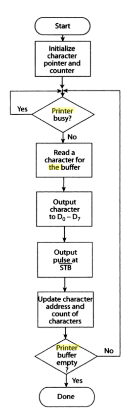
Let us now look at the sequence of events that take place at the parallel printer interface when data are output to the printer. Figure above is a flowchart of a subroutine that performs a parallel printer interface character-transfer operation. First the BUSY input of the parallel printer interface is tested.
Note that this is done with a polling operation. That is, the MPU tests the logic level of BUSY repeatedly until it is found to be at the not-busy logic level. Busy means that the printer is currently printing a character. On the other hand, not busy signals that the printer is ready to receive another character for printing.
After finding a not-busy condition, a count of the number of characters in the printer buffer (microprocessor memory) is read; a byte of character data is read from the printer buffer; the character is output to the parallel interface; and then a pulse is produced at STB.
This pulse tells the printer to read the character off the data bus lines. The printer is again printing a character and signals this fact at BUSY. The handshake sequence is now complete. Now the count that represents the number of characters in the buffer is decremented and checked to see if the buffer is empty. If empty, the print operation is complete. Otherwise, the character transfer sequence is repeated for the next character.
Here is the video description of how printer is interfaced with 8086/8088 Microprocessor.