Table of Contents
what is the serial communication?
what is the serial communication? Unlike parallel communication, where several bits are send at one time, Serial Communication is a process of transmitting data bit by bit. In this tutorial, you will learn how to serially communicate a PC or any other device with a PIC microcontroller. You will also study the use of a communication component – UART (Universal Asynchronous Receiver Transmitter) present within the microcontroller.
Serial vs Parallel Transfer:
PCs move information two way: sequential and parallel. In sequential Communication, just a solitary wire is needed to move n pieces of information or a couple of wires for prepared and recognize signals while in equal correspondence, and wires are needed to move n pieces of information. Sequential mode is utilized to move information to more noteworthy distances and equal just works for brief distances. Since more equipment is needed in equal correspondence mode, thus, sequential correspondence is liked. In information Transmission, if information can both be communicated and gotten, it is a duplex transmission. Interestingly, a simplex transmission just sends information from one gadget to the next, for example, from PC to printer. Duplex Transmission can be Half or Full duplex contingent on if the information move is concurrent. On the off chance that information is communicated each path in turn, it is half duplex. and the event that information can go the two different ways simultaneously, it is Full duplex. PIC microcontroller has a full-duplex, sequential method of Communication. Half and Full-Duplex Transmission.
What is SPI Communication Protocol?
The term SPI stands for “Sequential Peripheral Interface”. It is a typical correspondence convention that is utilized to send information between two microcontrollers or to peruse/compose information from a sensor to a microcontroller. It is likewise used to speak with SD cards, shift registers, Display regulators and substantially more.
How SPI Protocol Works?
The SPI correspondence is coordinated correspondence, which means it works with the assistance of a clock signal which is divided among the two gadgets that are trading the information. Additionally it a full-duplex correspondence since it can send and get information utilizing a different transport. The SPI correspondence requires 5 wires to work.
The five wires needed for the correspondence are SCK (Serial Clock), MOSI (Master Out Slave in), MISO (Master in Slave Out) and SS (Slave Select). The SPI correspondence consistently takes puts just between an expert and slave. An expert can have various slaves associated with it. The expert is answerable for creating the clock beat and the equivalent is imparted to all slaves. Additionally everything interchanges can be started exclusively by the expert.
The SCK pin (a.k.a SCL-sequential clock) shares the clock signal produces by the expert with the slaves. The MOSI pin (a.k.a SDA – Serial Data Out) is utilized to send the information from the expert to the ointment. The MISO pin (a.k.a SDI – Serial Data In) is utilized to get the information from the treatment to the expert. You can likewise follow the bolt mark in the above figure to comprehend the development of information/signal. At last, the SS pin (a.k.a CS – Chip select) is utilized when there are more than one slave modules associated with the expert. This in can be utilized to choose the necessary slave.
Difference between I2C and SPI Communication
We have as of now educated I2C correspondence with PIC thus we should be comfortable with how I2C functions and where we can utilize them like I2C can be utilized to interface RTC module. In any case, presently, for what reason do we need SPI convention when we as of now have I2C. The explanation is both I2C and SPI interchanges are benefits in its own particular manners and subsequently is application explicit.
To a degree the I2C correspondence can be considered to enjoy some upper hands over SPI correspondence on the grounds that I2C utilizes less number of pin and it gets convenient when there are countless slaves associated with the transport. However, the disadvantage of I2C is that it has a similar transport for sending and accepting information and thus it is relatively sluggish. So it’s absolutely founded on application to choose SPI and I2C convention for your task
UART Communication using PIC microcontroller
In this instructional exercise we figure out how to Enable UART correspondence with PIC Microcontroller and how to move information to and from your Computer. Up until now, we have covered all essential modules like ADC, Timers, PWM and furthermore have figured out how to interface LCDs and 7-Segment shows. Presently, we will furnish our self with another specialized apparatus called UART which generally utilized in the majority of the Microcontroller projects. Check here our total PIC Microcontroller Tutorials utilizing MPLAB and XC8.
Here we have utilized PIC16F877A MCU, it has a module called “Addressable Universal Synchronous Asynchronous Receiver and Transmitter” instantly known as USART. USART is a two wire correspondence framework in which the information stream sequentially. USART is additionally a full-duplex correspondence, implies you can send and get information simultaneously which can be utilized to speak with fringe gadgets, like CRT terminals and PCs.
The USART can be configured in the following modes:
- Asynchronous (full-duplex)
- Synchronous – Master (half-duplex)
- Synchronous – Slave (half-duplex)
There are likewise two distinct modes to be specific the 8-digit and 9-cycle mode, in this instructional exercise we will design the USART module to work in Asynchronous mode with
8-bit correspondence framework, since it is the most utilized kind of correspondence. As it is nonconcurrent it doesn’t have to convey clock message alongside the information signals. UART utilizes two information lines for sending i(TX) and accepting (Rx) information. The ground of the two gadgets ought to likewise be made normal. This sort of correspondence doesn’t share a typical clock subsequently a shared belief is vital for the framework to work.
Toward the finish of this instructional exercise you will be capable build up a correspondence (UART) between your PC and your PIC Microcontroller and flip a LED on the PIC board from your PC. The situation with the LED will be shipped off your PC from the PIC MCU. We will test the yield utilizing Hyper Terminal in PC. Definite Video is additionally given toward the finish of this instructional exercise.
Requirements:
Hardware:
- PIC16F877A Perf Board
- RS232 to USB converter Module
- Computer
- PICkit 3 Programmer
Software:
- MPLABX
- HyperTerminal
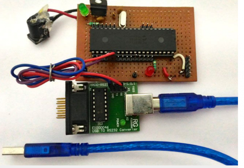
A RS232 to USB converter is required to convert the serial data into computer readable form. There are ways to design your own circuit instead of buying your own module but they are not reliable as they are subjected noise. The one which we are using is shown below
Note: Each RS232 to USB converter would require a special driver to be installed; most of them should get installed automatically as soon as you plug in the device. But, if it doesn’t relax!!! Use the comment section and I will help you out.
Also read here
Briefly write about all pins of LCD for connecting with the PIC microcontroller