What is UMTS?
What is UMTS? Universal Mobile Telecommunications System (UMTS) is envisioned as the successor to Global System for Mobile Communications (GSM). UMTS signals the move into the third generation (3G) of mobile networks. UMTS also addresses the growing demand of mobile and Internet applications for new capacity in the overcrowded mobile communications sky. The new network increases transmission speed to 2 Mbps per mobile user and establishes a global roaming standard.
UMTS, also referred to as wideband code division multiple access (W–CDMA), is one of the most significant advances in the evolution of telecommunications into 3G networks. UMTS allows many more applications to be introduced to a worldwide base of users and provides a vital link between today’s multiple GSM systems and the ultimate single worldwide standard for all mobile telecommunications, International Mobile Telecommunications–2000 (IMT–2000).
3G Systems are intended to provide a global mobility with wide range of services including telephony, paging, messaging, Internet and broadband data.
3GPP Radio Access group is responsible of:
- Radio Layer 1, 2 and 3 RR specification
- Iub, Iur and Iu Interfaces
- UTRAN Operation and Maintenance requirements
- BTS radio performance specification
- Conformance test specification for testing of radio aspects of base stations
- Specifications for radio performance aspects from the system point of view
3GPP Core Network group is responsible of:
- Mobility management, call connection control signaling between the user equipment and the core network.
- Core network signaling between the core network nodes.
- Definition of interworking functions between the core network and external networks.
- Packet related issues.
- Core network aspects of the lu interface and Operation and Maintenance requirements
3GPP Terminal group is responsible of:
- Service capability protocols
- Messaging
- Services end-to-end interworking
- USIM to Mobile Terminal interface
- Model/framework for terminal interfaces and services (application) execution
- Conformance test specifications of terminals, including radio aspects
3GPP Services and System Aspects group is responsible of:
- Definition of services and feature requirements.
- Development of service capabilities and service architecture for cellular, fixed and cordless applications.
- Charging and Accounting
- Network Management and Security Aspects
- Definition, evolution, and maintenance of overall architecture
UMTS Services
UMTS offers tele-services (like speech or SMS) and bearer services, which provide the capability for information transfer between access points. It is possible to negotiate and renegotiate the characteristics of a bearer service at session or connection establishment and during ongoing session or connection. Both connections oriented and connectionless services are offered for Point-to-Point and Point-to-Multipoint communication.
Bearer services have different QoS parameters for maximum transfer delay, delay variation and bit error rate. Offered data rate targets are:
- 144 kbits/s satellite and rural outdoor
- 384 kbits/s urban outdoor
- 2048 kbits/s indoor and low range outdoor
UMTS network services have different QoS classes for four types of traffic:
- Conversational class (voice, video telephony, video gaming)
- Streaming class (multimedia, video on demand, webcast)
- Interactive class (web browsing, network gaming, database access)
- Background class (email, SMS, downloading)
UMTS will also have a Virtual Home Environment (VHE). It is a concept for personal service environment portability across network boundaries and between terminals. Personal service environment means that users are consistently presented with the same personalized features, User Interface customization and services in whatever network or terminal, wherever the user may be located. UMTS also has improved network security and location based services.
UMTS Architecture
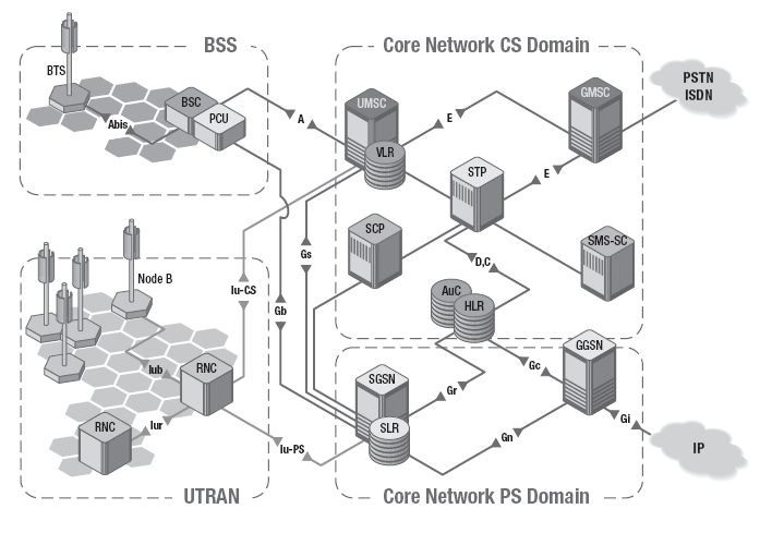
A UMTS network consist of three interacting domains; Core Network (CN), UMTS Terrestrial Radio Access Network (UTRAN) and User Equipment (UE). The main function of the core network is to provide switching, routing and transit for user traffic. Core network also contains the databases and network management functions.
The basic Core Network architecture for UMTS is based on GSM network with GPRS. All equipment has to be modified for UMTS operation and services. The UTRAN provides the air interface access method for User Equipment. Base Station is referred as Node-B and control equipment for Node-B’s is called Radio Network Controller (RNC). UMTS system page has an example, how UMTS network could be build.
It is necessary for a network to know the approximate location in order to be able to page user equipment. Here is the list of system areas from largest to smallest.
- UMTS systems (including satellite)
- Public Land Mobile Network (PLMN)
- MSC/VLR or SGSN
- Location Area
- Routing Area (PS domain)
- UTRAN Registration Area (PS domain)
- Cell
UMTS Core Network
The UMTS core network architecture is a migration of that used for GSM with further elements overlaid to enable the additional functionality demanded by UMTS.
In view of the different ways in which data may be carried, the UMTS core network may be split into two different areas:
-
Circuit switched elements:
These elements are primarily based on the GSM network entities and carry data in a circuit switched manner, i.e. a permanent channel for the duration of the call.
-
Packet switched elements:
These network entities are designed to carry packet data. This enables much higher network usage as the capacity can be shared and data is carried as packets which are routed according to their destination.
- Some network elements, particularly those that are associated with registration are shared by both domains and operate in the same way that they did with GSM.
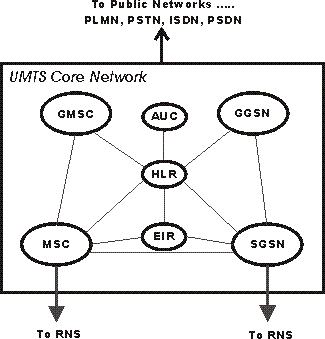
UMTS Core Network Circuit switched elements
The circuit switched elements of the UMTS core network architecture include the following network entities:
-
Mobile switching centre (MSC):
This is essentially the same as that within GSM, and it manages the circuit switched calls under way.
-
Gateway MSC (GMSC):
This is effectively the interface to the external networks.
The packet switched elements of the UMTS core network architecture include the following network entities:
-
Serving GPRS Support Node (SGSN):
As the name implies, this entity was first developed when GPRS was introduced, and its use has been carried over into the UMTS network architecture. The SGSN provides a number of functions within the UMTS network architecture.
-
Mobility management:
When a UE attaches to the Packet Switched domain of the UMTS Core Network, the SGSN generates MM information based on the mobile’s current location.
-
Session management:
The SGSN manages the data sessions providing the required quality of service and also managing what are termed the PDP (Packet data Protocol) contexts, i.e. the pipes over which the data is sent.
-
Interaction with other areas of the network:
The SGSN is able to manage its elements within the network only by communicating with other areas of the network, e.g. MSC and other circuit switched areas.
-
Billing:
The SGSN is also responsible billing. It achieves this by monitoring the flow of user data across the GPRS network. CDRs (Call Detail Records) are generated by the SGSN before being transferred to the charging entities (Charging Gateway Function, CGF).
-
Gateway GPRS Support Node (GGSN):
Like the SGSN, this entity was also first introduced into the GPRS network. The Gateway GPRS Support Node (GGSN) is the central element within the UMTS packet switched network. It handles inter-working between the UMTS packet switched network and external packet switched networks, and can be considered as a very sophisticated router. In operation, when the GGSN receives data addressed to a specific user, it checks if the user is active and then forwards the data to the SGSN serving the particular UE.
The shared elements of the UMTS core network architecture include the following network entities:
-
Home location register (HLR):
This database contains all the administrative information about each subscriber along with their last known location. In this way, the UMTS network is able to route calls to the relevant RNC / Node B. When a user switches on their UE, it registers with the network and from this it is possible to determine which Node B it communicates with so that incoming calls can be routed appropriately. Even when the UE is not active (but switched on) it re-registers periodically to ensure that the network (HLR) is aware of its latest position with their current or last known location on the network.
-
Equipment identity register (EIR):
The EIR is the entity that decides whether given UE equipment may be allowed onto the network. Each UE has a number known as the International Mobile Equipment Identity. This number, as mentioned above, is installed in the equipment and is checked by the network during registration.
-
Authentication center (AuC):
The AuC is a protected database that contains the secret key also contained in the user’s USIM card.
User Equipment
The UMTS standard does not restrict the functionality of the User Equipment in any way. Terminals work as an air interface counter part for Node-B and have many different types of identities. Most of these UMTS identity types are taken directly from GSM specifications.
- International Mobile Subscriber Identity (IMSI)
- Temporary Mobile Subscriber Identity (TMSI)
- Packet Temporary Mobile Subscriber Identity (P-TMSI)
- Temporary Logical Link Identity (TLLI)
- Mobile station ISDN (MSISDN)
- International Mobile Station Equipment Identity (IMEI)
- International Mobile Station Equipment Identity and Software Number (IMEISV)
UMTS mobile station can operate in one of three modes of operation:
- PS/CS mode of operation: The MS is attached to both the PS domain and CS domain, and the MS is capable of simultaneously operating PS services and CS services.
- PS mode of operation: The MS is attached to the PS domain only and may only operate services of the PS domain. However, this does not prevent CS-like services to be offered over the PS domain (like VoIP).
- CS mode of operation: The MS is attached to the CS domain only and may only operate services of the CS domain.
Radio Access
Wide band CDMA technology was selected to for UTRAN air interface. UMTS WCDMA is a Direct Sequence CDMA system where user data is multiplied with quasi-random bits derived from WCDMA Spreading codes. In UMTS, in addition to channelization, Codes are used for synchronization and scrambling. WCDMA has two basic modes of operation: Frequency Division Duplex (FDD) and Time Division Duplex (TDD).
What is UTRAN?
The UMTS standard can be seen as an extension of existing networks. Two new network elements are introduced in UTRAN, RNC, and Node B. UTRAN is subdivided into individual radio network systems (RNSs), where each RNS is controlled by an RNC. The RNC is connected to a set of Node B elements, each of which can serve one or several cells.
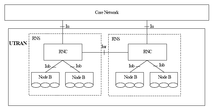
Existing network elements, such as MSC, SGSN, and HLR, can be extended to adopt the UMTS requirements, but RNC, Node B, and the handsets must be completely new designs. RNC will become the replacement for BSC, and Node B fulfills nearly the same functionality as BTS. GSM and GPRS networks will be extended, and new services will be integrated into an overall network that contains both existing interfaces such as A, Gb, and Abis, and new interfaces that include Iu, UTRAN interface between Node B and RNC (Iub), and UTRAN interface between two RNCs (Iur). UMTS defines four new open interfaces:
- Uu: UE to Node B (UTRA, the UMTS W–CDMA air interface
- Iu: RNC to GSM Phase 2+ CN interface (MSC/VLR or SGSN)
- Iu-CS for circuit-switched data
- Iu-PS for packet-switched data
- Iub: RNC to Node B interface
- Iur: RNC to RNC interface, not comparable to any interface in GSM
The Iu, Iub, and Iur interfaces are based on ATM transmission principles.
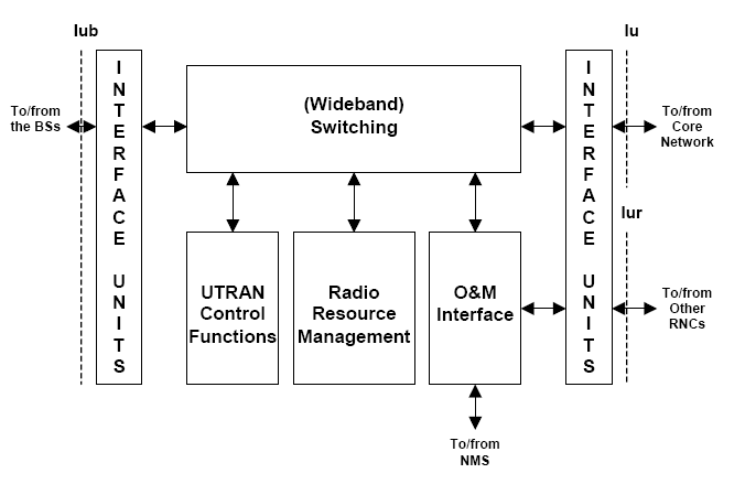
Radio Network Controller (RNC)
The RNC enables autonomous radio resource management (RRM) by UTRAN. It performs the same functions as the GSM BSC, providing central control for the RNS elements (RNC and Node Bs).
The RNC handles protocol exchanges between Iu, Iur, and Iub interfaces and is responsible for centralized operation and maintenance (O&M) of the entire RNS with access to the OSS. Because the interfaces are ATM–based, the RNC switches ATM cells between them. The user’s circuit-switched and packet-switched data coming from Iu–CS and Iu–PS interfaces are multiplexed together for multimedia transmission via Iur, Iub, and Uu interfaces to and from the UE.
The RNC uses the Iur interface, which has no equivalent in GSM BSS, to autonomously handle 100 percent of the RRM, eliminating that burden from the CN. Serving control functions such as admission, RRC connection to the UE, congestion and handover/macro diversity are managed entirely by a single serving RNC (SRNC).
If another RNC is involved in the active connection through an inter–RNC soft handover, it is declared a drift RNC (DRNC). The DRNC is only responsible for the allocation of code resources. A reallocation of the SRNC functionality to the former DRNC is possible (serving radio network subsystem [SRNS] relocation). The term controlling RNC (CRNC) is used to define the RNC that controls the logical resources of its UTRAN access points.
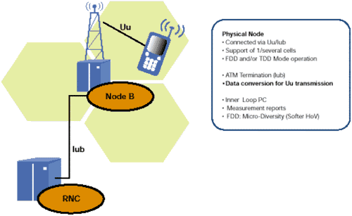
Define Node B
Node B is the physical unit for radio transmission/reception with cells. Depending on sectoring (omni/sector cells), one or more cells may be served by a Node B. A single Node B can support both FDD and TDD modes, and it can be co-located with a GSM BTS to reduce implementation costs. Node B connects with the UE via the W–CDMA Uu radio interface and with the RNC via the Iub asynchronous transfer mode (ATM)–based interface. Node B is the ATM termination point.
The main task of Node B is the conversion of data to and from the Uu radio interface, including forward error correction (FEC), rate adaptation, W–CDMA spreading/despreading, and quadrature phase shift keying (QPSK) modulation on the air interface. It measures quality and strength of the connection and determines the frame error rate (FER), transmitting these data to the RNC as a measurement report for handover and macro diversity combining. The Node B is also responsible for the FDD softer handover. This micro diversity combining is carried out independently, eliminating the need for additional transmission capacity in the Iub.
The Node B also participates in power control, as it enables the UE to adjust its power using downlink (DL) transmission power control (TPC) commands via the inner-loop power control on the basis of uplink (UL) TPC information. The predefined values for inner-loop power control are derived from the RNC via outer-loop power control.
UTRAN FUNCTIONS
Admission Control
The purpose of the admission control is to admit or deny new users, new radio access bearers or new radio links (for example due to handover). The admission control should try to avoid overload situations and base its decisions on interference and resource measurements. The admission control is employed at for example initial UE access, RAB assignment/reconfiguration and at handover. These cases may give different answers depending on priority and situation. The Admission Control function based on UL interference and DL power is located in the Controlling RNC. The Serving RNC is performing admission Control towards the Iu interface.
Congestion Control
The task of congestion control is to monitor, detect and handle situations when the system is reaching a near overload or an overload situation with the already connected users. This means that some part of the network has run out, or will soon run out of resources. The congestion control should then bring the system back to a stable state as seamless as possible. This admission Control function is related to Radio Resources. Congestion control is performed within UTRAN.
Radio channel ciphering and deciphering
This function is a pure computation function whereby the radio transmitted data can be protected against an unauthorized third-party. Ciphering and deciphering may be based on the usage of a session-dependent key, derived through signaling and/or session dependent information. This function is located in the UE and in the UTRAN.
Shared Networks Access Control
The Shared Networks Access Control function allows the CN to request the UTRAN to apply UE specific access control to LAs of the UTRAN and LAs of neighboring networks.
The Shared Networks Access Control function is based on either whole PLMNs or Shared Network Areas (SNAs). An SNA is an area corresponding to one ore more LAs within a single PLMN to which UE access can be controlled. In order to apply Shared Networks Access Control for the UTRAN or for a neighboring system, the UTRAN shall be aware of whether the concerned LA belongs to one (or several) SNA(s) or not.
If access for a specific UE needs to be restricted, the CN shall provide SNA Access Information for that UE. The SNA Access Information indicates which PLMNs and/or which SNAs the UE is allowed to access. Based on whether the LA belongs to the PLMNs or SNAs the UE is allowed to access, the UTRAN determines if access to a certain LA for a certain UE shall be allowed. If access is not allowed, the UTRAN shall prevent the UE to obtain new resources in the concerned LA.
Radio environment survey
This function performs measurements on radio channels (current and surrounding cells) and translates these measurements into radio channel quality estimates. Measurements may include:
- Received signal strengths (current and surrounding cells);
- Estimated bit error ratios, (current and surrounding cells);
- Estimation of propagation environments (e.g. high-speed, low-speed, satellite, etc.);
- Transmission range (e.g. through timing information);
- Doppler shift;
- Synchronization status;
- Received interference level;
- Total DL transmission power per cell.
This function is located in the UE and in the UTRAN.
CBS Status Reporting
The RNC collects status data per cell (e.g. No-of-Broadcast-Completed-List, Radio-Resource-Loading-List), and matches these data to Service Areas. The status data is transmitted to the CBC, if a query has been made by the CBC.
Tracing
This function allows tracing of various events related to the UE and its activities.
Also read here
https://eevibes.com/computing/object-oriented-programming/what-is-the-switch-statement-in-c/