Introduction
In this article I have descried how to Design of a 3-bit Up Counter using JK Flip-Flop. 3 bit up counter is a synchronous counter that uses three bits at the output for producing the values from 000 to 111. It is called up counter as its values are incremented from 0 to 1 to 2 ….till 7.
3 JK flip flops are used for representing each bit. The possible states can be determined using the formula:
23=8
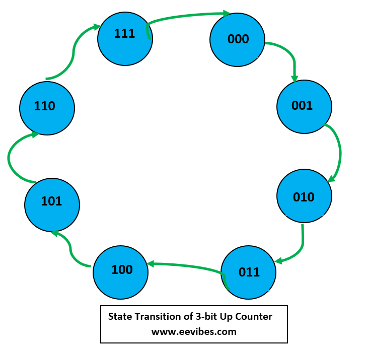
(000 → 001 → 010 → 011 → 100 → 101 → 110 → 111 → 000)
The name synchronous is given since all the flip flops are triggered by the common clock signal.
Design Steps of 3-bit Up Counter
The first step is to understand the truth table of JK Flip Flop
| J | K | Qn+1 |
| 0 | 0 | Qn |
| 0 | 1 | 0 (Reset) |
| 1 | 0 | 1 (set) |
| 1 | 1 | (Qn)’ Toggle |
After that, we will design the excitation table for a single flip flop

From the above table we can notice that when Qn and Qn+1 are both zero (no change in state) then the possible input combinations are (J=0, K=0 or since Qn+1 is 0 (Reset State) so J=0 and K=1). This simply implies that J must be equal to 0 while K can be either 0 or 1 (so dont care condition for K as depicted in the above table). Similarly, for Qn =0 and Qn+1 =1, there is the change in state (from 0 to 1) so this is possible when both inputs are equal to 1 or when flip flop is in the set state (J=1, K=1 & J=1, K=0). This combination results in J=1 and K=x (dont care again. The same is true for rest of the two combinations.
The simplified excitation table is shown below:
| Qn | Qn+1 | J | K |
| 0 | 0 | 0 | x |
| 0 | 1 | 1 | x |
| 1 | 0 | x | 1 |
| 1 | 1 | x | 0 |
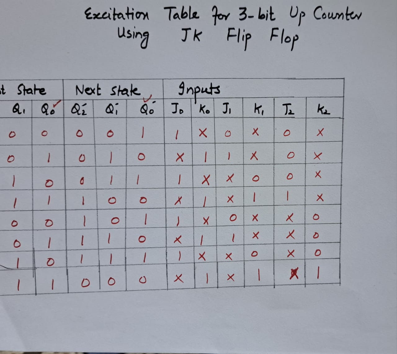
Now, we can determine the input combinations for all three flip flops as depicted below:
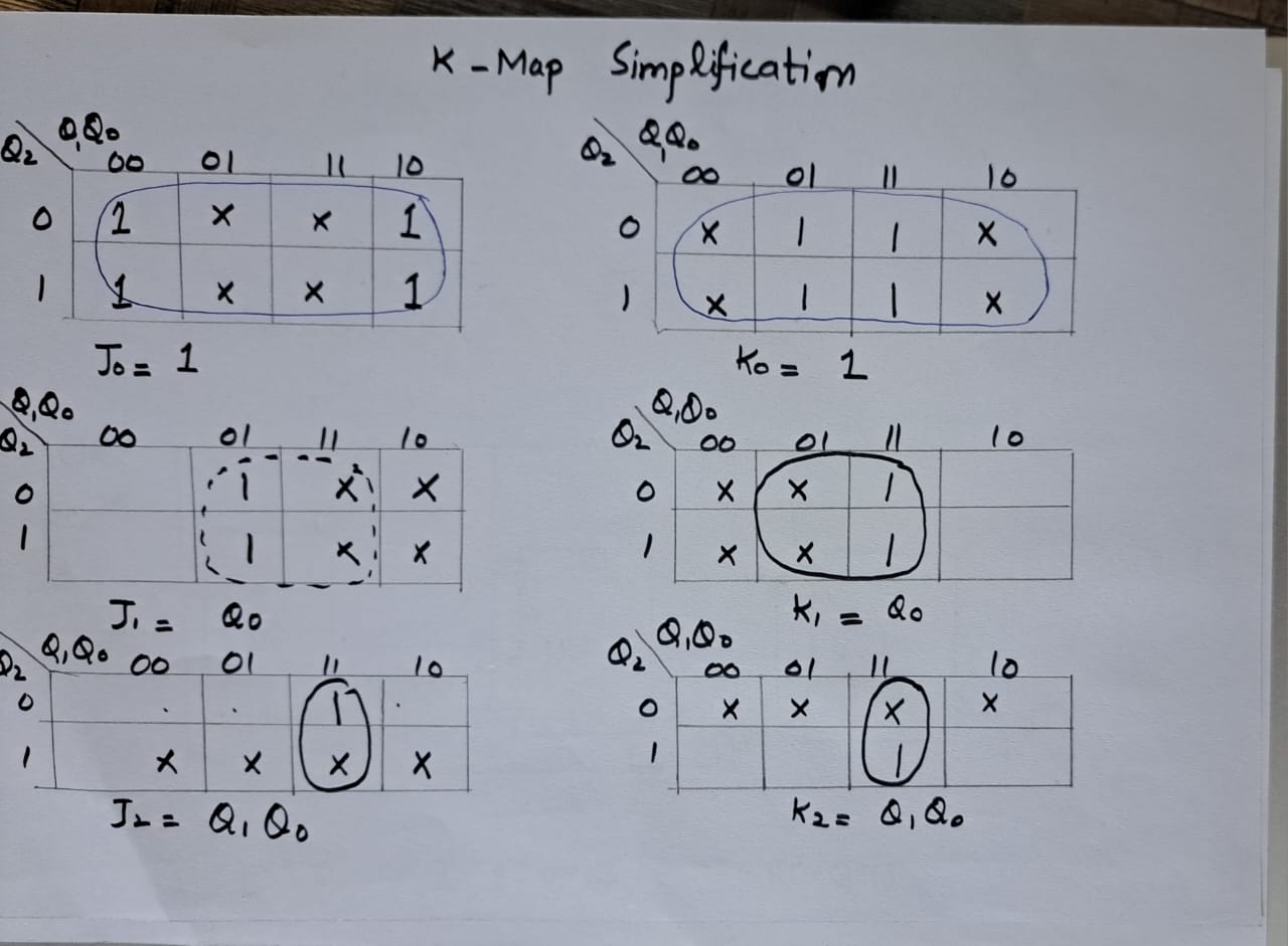
Derivation of Input Equations Using K-Map
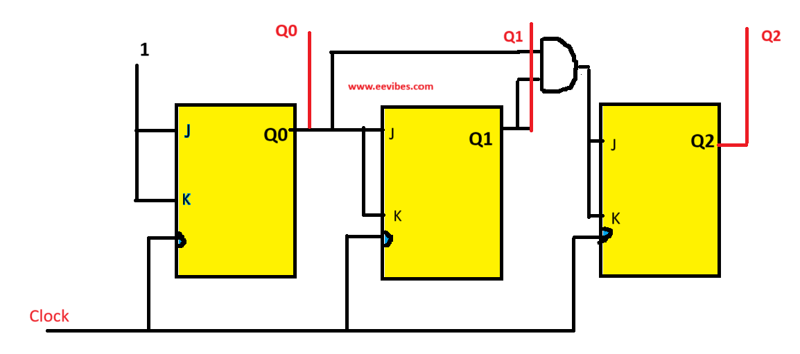
Finally, you can draw the circuit diagram for it.