Introduction to elevator control system
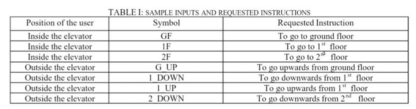
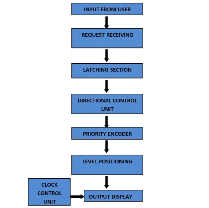
How elevator control system works? A simulation study of an elevator control system of a 3-storey building has been defined and implemented in this research paper. Major sections of the whole circuit structure are as input unit, directional control unit, priority encoder (to prioritize the requests, level positioning control unit, output display and clock controlling unit. Simulated results from the circuit simulator software show exact match with the desired results which proves the design validity.
Elevators that are also commonly called as lifts are a form of vertical transport. It is inseparable part of a building structure. They are used to transport both people and goods from one floor to another. Elevators are also seen in large ships with so many topsides.
Just the invention of awesome building materials such as steel and concrete was not amazed people but it was the invention, of the safe, reliable elevator by Elisha Graves Otis of Yonkers, New York in 1867.
A simulation study of elevators in a three story building is presented in this paper using digital logic circuit. Elevator control system of a building has been proposed earlier in some literatures. But the unique aspect of this paper work is that any Microcontroller or Programmable Logic Controller are not used for logic implementation in this design, rather the logic equations are developed by using basic digital logic circuit components. To form the logic equation to determine whether the present direction of the lift will be upward or downward, the probable events (requests from users for upward or downward movement of lift) are identified and used as variables for logic equation. In this logic equation, the requests will be served on the priority basis.
Sample inputs
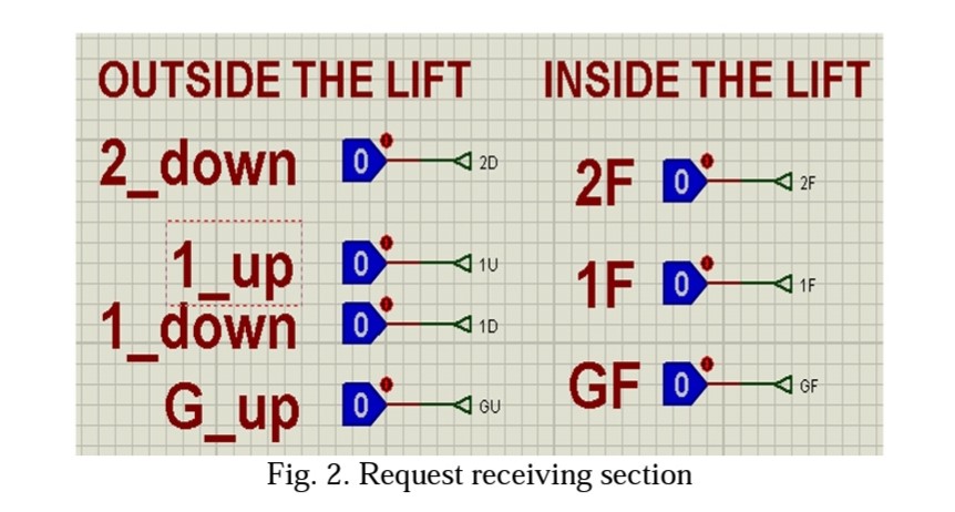
Inputs to an elevator user standing inside or outside of a three story building elevator have been displayed in the table given below.
Terminologies
The terminologies used in our research paper are described below:
Proteus 7 Professional
The Proteus 7 professional is a software which is used initially for electronic design automation. Mainly the electronic design engineers and technicians used this software to create schematics and electronic prints for creating printed circuit boards. It was developed in Yorkshire, England by Lab center Electronics Ltd and is available in English, French, Spanish and Chinese languages.
Logic Toggle
Logic Probes are also the Boolean devices and to give the Input to logic circuits they are used. They just have two conditions and through a small arrow presented on one side of the Logic Toggle we can switch the input from HIGH to LOW or vice versa.
Seven segment display
Seven different illuminating segments are used to make 7 segment display. By displaying different combinations of segments these are arranged in a way to form numbers and characters. Using these seven segments the binary information is displayed . To display the required numeral or alphabet the LED’s or LCD’s are used.
Circuit design description:
Input unit
Input unit consists of two major sub units:
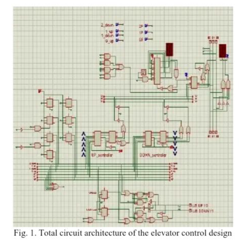
Request receiving section and latching section. The requests listed in Table, are taken from the user using LOGICTOGGLE a Boolean device at Proteus 7 Professional. It acts as the request receiving section of the input unit.
Since a number of instructions can be requested at a time so the rest of the instructions must be saved using a latching section and they must be served on priority basis,. In our design, we have used J-K flip-flops as the latching section. Since the two inputs of the flip-flops are shorted together and assigned a constant logic level 1, so it essentially works as a T flip flop. The inputs from the request receiving section work as the clock of the flip-flops. If any particular request is made twice consecutively, the clock pulse of the flip-flops works the same way consecutively and because of the consecutive toggling of data at J-K flip-flop, that particular request is reset. It resembles to an event if a user mistakenly requests an event and wants to cancel the request by pressing the request button for the second time.

Directional control unit
Directional control unit helps to decide the up or downward direction of the lift . The buffers are used in this unit. These buffers are used to avoid the race condition (two logic levels at the same node). since at each instant upward and downward values are changed and only one of them should send level positioning data.
Priority encoder
The next step is to set the priority of the requests stored in the latching section after the deciding the movement of the lift . Priority encoder used for this purpose. Two priority encoders have been used to assign the priority of the events that can happen associated with both the upward and the downward direction of the elevator. To build the level positioning control unit to determine the current position of the lift, the 3 bit outputs from both the priority encoder helps.
Level Positioning control unit
Level positioning control unit is based on two decoders and buffer circuits. It determines the current level position and sends the data to central bus to display it to the output section. The two different logic levels are not encountered at central bus, Buffers are enabled by logic state of upward or downward .
Output display unit
In the output display current level position determined by the level positioning control unit will be displayed. By a clock control unit, the fixed delay is set. Final output display is shown in a BCD 7-segment display.
Clock control unit
Clock controlling unit controls fixed delay between consecutive requests. Successive requests are served with a 10s delay in between them which resemble to transition of the elevator between the floors.
Functional Block Diagram
Conclusion
A building to work efficiently and safely good elevator plan helps. This means moving through the building and using the elevators, passengers enjoy a good experience.
It can lead to costly delays later in the process, if elevator design isn’t handled correctly from the outset. Any mistake or blunder in designing the elevator can lead to the loss of many human lives
Future work
The future of elevators is now the present and it is damned wild.
Multi elevator
The multi elevator which is a few years ago cannot be even supposed and not ever heard is now announced by a company ThyssenKrupp. Everyone knows elevators just go up and down and when ThyssenKrupp ( a German multi national) announced developing of such a multi elevator which goes to every direction (up, down, left, right, even diagonally) people laughed.
After three years of work the company is testing the multi in a German tower and finalizing the safety certification. And ThyssenKrupp has sold it to a under construction building.
Zero Touch Controls
In public elevators post Covid-19,surface hygiene inside elevator has become really very important. This is because you never know who may be infected with the Coronavirus and the elevators in commercial or public buildings host visitors from all over.
That’s why to reach the floor you want to get to newer elevators may allow you to enter your destination either via a digital app installed on your smartphone or a panel outside an elevator cab, instead of touching manual control panels. Doors will open automatically and all you have to do is enter and stand in a designated spot for the duration of the travel.
Some elevator systems are also considering control panels allowing you to kick in the number of the floor you want instead of pressing it with your fingers, located near the bottom of the elevator wall panel.
The future of smart elevator technology is up.
Also read here
https://eevibes.com/computing/object-oriented-programming/how-to-darken-an-image-using-css/