Introduction:
What are the applications of digital logic design? The fundamentals and implementation of digital logics are essential to understanding the design and working of consumer/industrial electronics, communications, computers, security and military equipment. Digital electronics includes many applications in real life. Here are three different and most important application of Digital logic design.
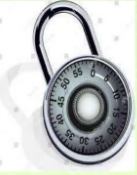
Simple Combination Lock
This is a simple but effective code lock circuit that has an automatic reset facility. Using XOR gates as bit comparators and Build simple gate functions with diodes and a pull up/down resistor. Using NOR gates as controlled inverters.

Working:
First we need a circuit to decode 10 possible inputs (0-9) to 4 BCD outputs (binary decimal) and another output that tells us when the button is pressed. Next, we need to build a circuit for our two 7-segment monitors so that they function properly, with 4 inputs for the BCD number and of course 7 outputs for our monitors (with IC 74LS47). Then the scheme for storing each entered number and to switch between screens. As well as our internal password memory And our lock fireplace, comparator (it’s 8 bits, because there are 4 bits per digit on the screen, which means that if you want to do a 4-digit lock, you have to connect two of these). The screen numbers indicate whether the same passwords are stored in the internal memory. And finally, the signal opens or closes indefinitely, and of course the output (that’s all you need to control with your key).
Advantages:
- It cannot be picked
- There is no key issue
- Just memorize the combination
Disadvantages:
- the battery can die
- the thief can obtain combination by different ways
- He can guess, sometimes it works
A Digital Stopwatch:
A digital stopwatch circuit can be worked as a clock in this counter will advance after every one second.

Components for circuit:
ICs that are used are:
- CD4060BM-14 stage ripple carry binary counter-1
- CD4040BM-12 stage ripple carry binary counter-1
- NE-555-Timer 1
- MC14158B- BCD counter-1
- MC14511B-BCD to seven segment display driver 2
Circuit Schematic:

Working:
The circuit operation begins once open switch is changed to closed position.
Timer 555 IC provides pulse to start operation. This signal is used to regulate the BCD CD14510 sport phase. The IC CD4510 is equipped with 4 D flips synchronized with the operating base for its operation. Pulse of numeric clock having a two-phase synchronous adjustment of two CD45 10 counters. For IC U3, the pulse of the number is 0, followed by the number 0 by 9. Passing the number 9, IC U4A and port I will continue to be identified in the future of IC U2. Scale and operation number of IC U2. IC U2 continues with the counting operation, as does IC U3, each time U3 reaches the final number. The trigger on the MC14518 counter will increase by 1 if we give it a pulse. Therefore, by replacing the 1 Hz pulse generator circuit with a photosensor, the circuit can be used as a “photometer”. The circuit can be used as a “human counter” using two IR sensors. The circuit can also be used as a “countdown” or “alarm clock”.
Limitation:
- The circuit cannot display the real time
- The use of ICs provide time delay in operation
- It’s a theoretical circuit and require changes
Smart Card:
It has a chip with an integrated circuit memory microprocessor Exchange will store data and manipulate data

Working:
It Connected to host computer. The card reader receives information. The host sends the information to the computer.
Advantages:
- Might be promptly reconfigured
- Reusable
- Secure transactions
- Gives more security
- More tough and dependable Permit numerous provisions to be saved in one card
Smart card use
- Telecommunication
- Domestic
- Ecommerce and Retail
- Banking Application
- Secured physical Access
Also read here
https://eevibes.com/mathematics/standard-deviation-sample-population-explained-with-examples/
Standard deviation (Sample & Population) explained with examples