Table of Contents
Introduction to problem
what is 2–digit Electronic Lock System? Despite all sorts of security gadgets and locks, the rising rate of crime, as well as attacks by thieves, intruders, and vandals, researchers must continue to focus on finding a lasting solution to ensure the safety of people’s lives and property. To this purpose, we create a low-cost, high-performance security system for buildings, cars, safes, doors, and gates that uses electronic devices as locks to prevent unwanted access to one’s property. The design, on the other hand, took a modular approach, with the combination lock being divided into units and each unit being designed separately before being combined to form a complete functional system.
This paper describes the design, manufacture, and deployment of a 2-digit electronic locking system for crime and intrusion prevention. Simple circuit elements were used to design and construct the electronic locking system, which was then implemented using digital electronic logic gates. The electronic lock accepts a 2-Digit code, compares it to the stored code in its memory through a comparator, and turns on or off any connected device if the two codes match or mismatch. The device makes use of a keypad for data entry achieved with a Binary Coded Decimal (BCD) Encoder IC (74C922), a set of shifts register ICs (4035B) for memory and a set of 4001 quad NOR and 4070 quad EX-OR logic gates for comparing and a relay for switching. During testing, the result showed that the device switches ON or OFF any electronic device connected to it if both codes match or mismatch.
Introduction:
This paper describes the design, manufacture, and deployment of a 2-digit electronic locking system for crime and intrusion prevention. Simple circuit elements were used to develop and create the electronic locking mechanism, which was then implemented using digital electronic logic gates. The electronic lock accepts a 2-Digit code, compares it to the stored code in its memory through a comparator, and turns on or off any connected device if the two codes match or mismatch.
The code unit, which operates with a 10-switch keyboard was designed to control an electromagnetic door lock with a four– digit code. Unlike other keyboard combination locks this lock is constructed in such a way that once any of the wrong keys is pressed, it resets automatically making it harder for an intruder to break into. This paper describes the design, manufacture, and deployment of a 2-digit electronic locking system for crime and intrusion prevention. Simple circuit elements were used to develop and create the electronic locking mechanism, which was then implemented using digital electronic logic gates. The electronic lock accepts a 2-Digit code, compares it to the stored code in its memory through a comparator, and turns on or off any connected device if the two codes match or mismatch.
Locks have been continuously enhanced by the incorporation of various materials, resulting in increasingly sophisticated working mechanisms, including the installation of automatic electronic alarm and safety. Depending on the security requirements of the intended application, electronic locks come in a variety of levels of intricacy, versatility, and adaptability. As a result, DNA Sensor Locks, Card Sensor Locks, Electronic Eye Locks (Retina Scanners), Thumbprint Sensor Locks, and Electronic Combination Locks are all examples of this type of lock. As a result, electronic locks have been dubbed “the most elegant of all locks” (Rashid, 1986).
We designed, built, and tested a two-digit electronic combination lock system that can be utilized to replace mechanical combination locks in this project. The electronic lock accepts a number combination via the keypad, records it in shift registers for storage, compares it to a previously saved input using logic gates, and then turns on and off any devices linked to it. Despite the lack of programming and microcontrollers in the design, the lock is still adaptable since any 2-digit combination can be used as the secret combination rather than a pre-coded combination that can only be changed by altering the related electronics.
This makes it simple for the user to change the lock’s secret combination if it is hacked. Because the design relies on simple circuit parts and integrated circuits, programming is not required to demonstrate basic digital electronics circuitry principles. This is an excellent teaching tool for academics. Because the lock is open-ended and uses a relay, it may be integrated into any electronic device, allowing it to be used in electronic or electrical systems, such as attaching a lock to a media player or television set.
Materials and Methods:
The design of this lock is based on digital electronics – the branch of electronics which uses binary systems. The lock is primarily composed of 4 units which are the keyboard, the memory, the comparator and the lock unit as illustrated. The power supply for the device was 9volts direct current (DC) from battery cells. A code is entered through the keyboard into the memory of the device The comparator compares whether the entered code matches the previously entered code (pre-set or key code) and it indicates the result by lighting up the appropriate LED and energizing a relay which either locks or releases an attached electronic device.
Keypad:
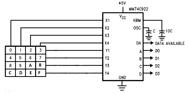
The device’s input is a keypad, which consists of a matrix of switches organized in a 4 by 4 matrix to represent the numbers 0 to F in the Hexadecimal numbering system (Base16). The switches are coupled to a 74C922 self scan IC Encoder and capacitors, which produces a binary output depending on which key(s) is pressed. The 74C922 looks for key enclosure by continually scanning the keys on the keypad. When a closure is identified, it is de-bounced and, if legitimate, the output is given. The encoder is coupled to capacitors, which control the pace at which the encoder scans the key pad. The keypad’s output is sent into a shift register, which serves as the memory. The 74C922 encoder, to which a set of switches organized in a 4 x 4 matrix are linked, lies at the heart of the keypad. A hexadecimal input is encoded into a four-bit binary output by the encoder’s eighteen (18) pin IC. The inputs are provided by sixteen switches (labelled 0 to 9 and A to F) coupled in a four-row, four-column matrix, resulting in only eight connections to the IC. C1 is an external capacitor whose value (0.01 uF) determines the rate at which the fast oscillator in the IC scans the switches to identify the pressed key. The additional external capacitor, C2 (0.1 uF), prevents the switches from bouncing when two contacts are pushed together. They don’t make a sequence of quick, faulty connections at initially, instead producing random, unwanted pulses. Except for C2, the IC has a circuit to avoid this. The IC outputs the corresponding high and/or low output in binary through pins 19, 18, 17, 16 depending on which switch is pressed (LSB-MSB).
Memory unit:
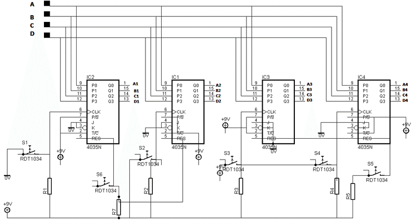
The memory is made up of a series of shift registers that store the data from the keypad. The two-digit keycode is represented by one pair, while the entered code is represented by the other pair. Shift registers, resistors, and switches made up the memory unit. The first and second pairs of digits were stored in the device using two pairs of 4-bit parallel-in parallel-out (input and output) shift registers (IC 4035B). The shift registers’ inputs are pins 9, 10, 11, and 12, while pin 6 is the clock pulse, which is coupled to the positive via a switch and a pull down resistor. The pin is ordinarily ‘LOW’ until the switch is pressed and released, at which point it switches from ‘LOW’ to ‘HIGH’ and back to ‘LOW’. The states of the input pins are transferred to the output pins 1, 15, 14, 13 once this switch is pressed, and this can be reset by pressing the switch attached to the reset pin 5 as was done with pin 6. The reset sets all of the output pins to ‘LOW’. The Reset pins of each pair of codes were wired together, but the Enter keys (switch to pin 6) for each of the registers were wired separately. The positive rail was connected to pins 2, 7, 16, while the negative rail was attached to pins 3, 4, 8.
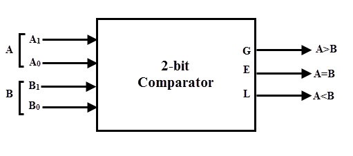
The digital Comparator:
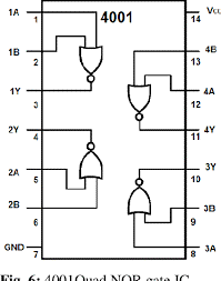
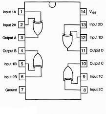
As Bit comparators, the circuit employs XOR (Exclusive-OR) gates. There are four of these XOR gates (in a single IC 4070 ). Compare the bits of two 4-bit binary numbers that come from the shift registers’ output. A Green LED will light up if the two numbers match bit for bit, and a Red LED will light up if they do not. If the input signals are not of the same logic state, XOR gates produce a ‘HIGH’ signal. A diode network was used to connect the output terminals of the eight XOR gates, resulting in an 8-input OR gate. If one of the eight XOR gates outputs a ‘HIGH’ signal, indicating that the entered code and the key code are not the same, the ‘HIGH’ signal is transferred to the NOR logic gates (in the 4001Quad NOR gate IC). The XOR gate outputs will be ‘LOW’ if the pair of two 4-bit codes is identical, and the pull-down resistor linked to the common sides of the diodes will send a ‘LOW’ signal state to the NOR logic. When the output of the XOR gate is ‘LOW,’ the NOR logic turns on the Green LED, and when the output of the XOR gate is ‘HIGH,’ the NOR logic turns on the Red LED.
Results:
The following are the results of the device’s testing and demonstration. By pressing the first digit, then the enter key for the second, a two-digit code was entered. The gadget switches to lock mode when the two numbers are placed in the shift registers. The relay disconnection occurs, and the RED LED indicator illuminates. The same two digits must be entered one after the other to unlock the device as they were the first time. The relay connects in this situation, and the GREEN LED indicator illuminates. When a key on the keyboard is pressed, the encoder’s four outputs go HIGH or LOW. If you press ‘3’, for example, A and B will be HIGH, while C and D will be LOW. The keypad’s binary output is applied to the four shift registers’ inputs. Because they are all connected to the negative through 10K resistors, the clock input (pin 6) on the shift register is normally LOW. When a register’s entry key is pressed, the resulting rising edge from 0 to 9V shifts the HIGH or LOW states of the register’s four inputs to the output. As a result, the register’s output states are A=1, B=1, C=0, and D=0. However, unless the ‘Enter’ button is pressed before they assume the state of the key pressed on the keypad, the other outputs of the other shift registers stay 0 or in their prior state.
Conclusion:
The proposed and built 2-digit lock worked as expected, and the goal of using fundamental digital electronics to design a complicated electronic lock was met. The device’s components are freely available on the market, making it simple for students and academics to acquire and use to demonstrate digital electronic principles. The proposed ele–ctronic lock is a good teaching resource for digital electronics as well as an efficient and ideal means of regulating access to electronic devices, machinery, and physical facilities. More digits can be added to the lock to increase its strength, which can be done by adding more bit comparators. However, this will result in an increase in the size of the circuit as well as the overall number of components. The long described in this study is less expensive than locks of comparable complexity produced using other methods.
Futurework:
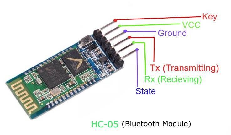
Bluetooth Module HC-05
Bluetooth module is used for wireless transmission. Its range is 10 meters. This module is based on Cambridge silicon radio BC417 2.4Ghz Bluetooth chip. It is a complex chip which uses an external 8 bit flash memory. It is a small module which works on very less power that is 3.3V. It has transmitter (Tx) and receiver (Rx) pins which are used for the transmission of data. The Tx of the module is connected to the Rx of the Arduino and Rx of the module is connected to the Tx of arduino.
Arduino
Arduino is an open source platform used for building electronics project. Arduino is often referred as a microcontroller. Different types of Arduino and Microcontroller boards are available, we preferred the two different Arduino boards and its specifications are as follows: • ATmega328 Boards : 32kB Program Space, 1 UART, 6 PWM, 4-8 Analog Inputs, 9-14 Digital I/O ports. Keypad/Bluetooth/GSM Based Digital Door… 751 • ATmega2560 Arduino Mega: 256kB Program Space, 4 UARTs, 14 PWM, 16 Analog Inputs, 54 Digital I/O ports.
Also read here
how to design and manufacture electrostatic MEMS relay for high power application?