Series and Parallel Resistance calculator Online
Series & Parallel Resistor Calculator
This tool helps you to calculate the series and parallel combination of resistance and gives the the final result. The measure of opposition to electric current in an electric circuit is known as electrical resistance. In common words it can be described as the force which a resistor uses to stop the flow of current flowing across it. In some cases, it is also defined as the ratio between the potential difference or voltage applied across the resistor to the current flowing through it. Another term which is the exact opposite of resistance is known as electrical conductance. It is the perfect reciprocal of resistance. The formulas for both the quantities as given as
R=V/I
G=1/R=I/V
The SI unit of electrical resistance is Ohm (Ω) while electrical conductance is measured in Siemens (S)
If one looks deeply at the concepts of resistance, one can compare it with the concepts of mechanical friction. The resistance of an object largely depends upon the type of material used in its manufacturing. Objects composed of insulating materials offer a very high resistance while those having a great ratio of conducting materials offer a very low resistance.
This nature of materials affecting the overall resistance of a substance if qualified by resistivity or conductivity. These two are also important terms which are used if one is dealing with materials with strange resistive or conductive behavior. However, the nature of material is not the only quantity affecting the resistance, it is also affected by the size and shape of the object because these qualities are rather extensive. For example, a long and thin wire offers high resistance and low conductance while a short and thick wire offers low resistance and high conductivity.
Power Dissipation of a Resistor
Resistance is the property of a body that transform electrical energy in heat energy. This phenomenon can be easily understood. As resistor offers opposition to the flowing current, as a result of this opposition, resistor gets heated because of the heat generated inside the resistor. Thus we can easily conclude that resistor is a source for converting electrical energy into heat energy. Resistance involves collision of current-carrying charged particles with fixed particles situated inside conductor. Resistance is sometime regarded as localized in some devices such as lamps, heaters and resistors. Although it is the characteristic part of almost every circuit, if there is not voltage drop across a resistor in a circuit, the current will not dare to flow.
The heat dissipated inside the resistor, in a small amount but, affects the amount of electromotive force, or driving voltage, required to produce a current to flow in the circuit. In fact, the electromotive force inside the circuit divides the current evenly in the circuit that quantitatively defines the amount of resistance.
The resistance of a conductor, or any circuit element, generally increases with increasing temperature. Upon cooling, some circuit elements show a non-responsive behavior and show zero resistance.
What is the Ohm’s Law?
One of the most important concept in the field of electrical engineering and electronics. For many materials, the CURRENT I flowing through the material is directly proportional to the APPLIED VOLTAGE V across it over a wide range of voltage and current. Mathematically
I∝V
Then
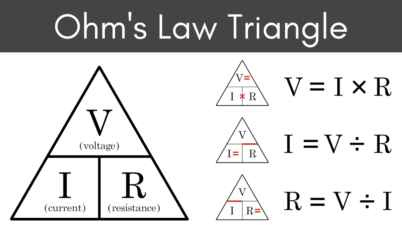
I=V/R
Thus according to the formula, a direct form of relation can be seen between the voltage applied and current flowing. The resistance or conductance of electronic components inside a circuit remains constant. This relationship is called OHM’S LAW and the materials that obey ohm’s law are called ohmic materials. Similarly, those materials that do not obey ohm’s law are called non-ohmic materials.
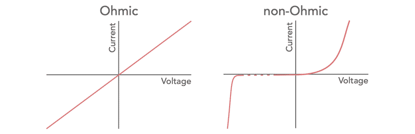
The graph of an ohmic material consists of a straight line that goes straight towards a positive slope. While the non-ohmic materials, as they do not obey ohm’s law, don’t form a similar graph rather they constitute a quite invariable and unpredicted graph.
What is the Resistivity and Conductivity?
The resistance of a given object depends primarily on two factors: type of material and the physical properties. The resistance is inversely proportional to the cross-sectional area. Thus for a thick wire the resistance would be minimum. Also the resistance has a direct relation with the length of the material used. A longer wire offers more resistance than a shorter wire. Now formulating these statement for formula generation for both resistivity and conductivity
R=ρ L/A
G=σ A/L
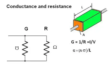
Where L is the length of the conductor and A is the cross sectional area. ρ (rho)is the electrical resistivity measured in ohm-meter and σ (mho)is the electrical conductivity measured in Siemens per meter. The resistivity and conductivity are the proportionality constants and depends largely on the nature of the material and not the geometry of the material. Like resistance and conductance, resistivity and conductivity are also the reciprocal of each other.
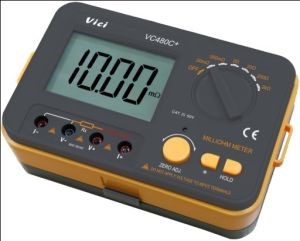
How to Measure the Resistance?
As voltmeter is used for measuring voltages and ammeter is used for measuring current, similarly, ohmmeter is used for measuring resistance. Some resistances are small enough that the normal ohmmeter cannot measure them thus for precision a 4-digit ohmmeter is used for the purpose.
Types of Resistances
Depending on the types of function resistance is divided in to two major types
What is the Static Resistance?
It is also referred to as chordal of DC resistance. Simply it is the basic type of resistance we have been studying up till now. This points to the basic definition and concepts of normal resistance i.e. voltage divided by current
R=V/I
Static resistance determines the power dissipation in an electrical circuit when it is connected to a DC source. Its graph curve is same as that of a normal resistance.
What is the Dynamic Resistance?
Also called as differential or incremental or small-signal resistance. Dynamic resistance is defined as the derivative of voltage with respect to the current: the slope of the current-voltage curve at any point in the graph
R_dyn=dV/dI
If the current-voltage graph has a negative slope, then we would have a negative differential resistance. Devices with negative differential resistance are able to amplify any incoming signal and thus come in handy when making amplifiers and oscillators.
Series and Parallel Combination of Resistors
The combination rules for any number of resistors in series or parallel can be derived with the help of OHM’S law, the voltage law and the current law.
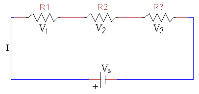
Series Combination of Resistance
In series combination, the current in the circuit remains constant thus the total equivalent current will be equal to
$$
I_{E Q}=I_1=I_2=\cdots=I_N
$$
While the voltage in the series combination changes and the equivalent voltage is equal to the sum of all the individual voltage drops across each resistors
$$
V_{E Q}=V_1+V_2+\cdots+V_N
$$
The equivalent resistance is given by the individual sum of all the resistances
$$
\begin{gathered}
R_{E Q}=R_1+R_2+\cdots+R_N \\
R_{E Q}=\frac{V}{I}=\frac{V_1+V_2+V_3+\cdots+V_N}{I} \\
R_{E Q}=\frac{V_1}{I_1}+\frac{V_2}{I_2}+\frac{V_3}{I_3}+\cdots+\frac{V_N}{I_N} \\
R_{E Q}=R_1+R_2+\cdots+R_N
\end{gathered}
$$
Parallel Combination of Resistors
In parallel combination, the voltage applied across each resistor remain same throughout whereas the current in the circuit changes. The current drop across each resistor is not same.
$$
I_{E Q}=I_1+I_2+\cdots+I_N
$$
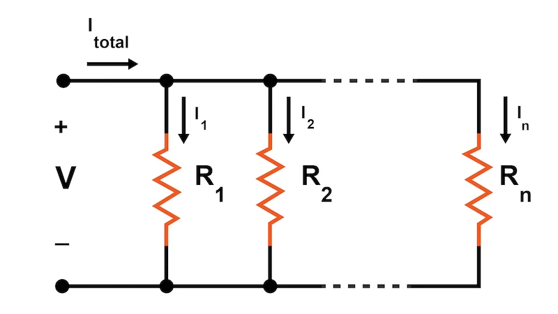
As the voltage in parallel combination remains same, thus it is given by
$$
V_{E Q}=V_1=V_2=\cdots=V_N
$$
The equivalent resistance in parallel combination is given by
$$
\begin{gathered}
\frac{1}{R_{E Q}}=\frac{1}{R_1}+\frac{1}{R_2}+\cdots+\frac{1}{R_N} \\
R_{E Q}=\frac{V}{I}=\frac{V_1}{I_1}+\frac{V_2}{I_2}+\frac{V_3}{I_3}+\cdots+\frac{V_N}{I_N} \\
\frac{1}{R_{E Q}}=\frac{1}{R_1}+\frac{1}{R_2}+\cdots+\frac{1}{R_N}
\end{gathered}
$$
Also read here: