Introduction
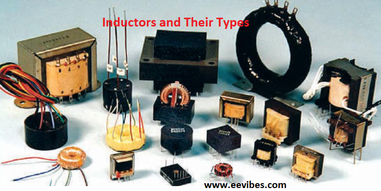
What are Different Types of an Inductor? An inductor is a coiled structure commonly used in electronic circuits. A coil is a loop of insulated wire wrapped around a central core. Inductors are commonly used to reduce or control electrical transients by temporarily storing energy in an electromagnetic field and releasing it into the circuit. This is actually the opposite of a capacitor. Their functions are completely different. However, both components are often used for multifunctional purposes.
What is an Inductor?
An inductor is a passive electrical component consisting of a coil that exploits the relationship between magnetism and electricity due to the current flowing through the coil. When electricity is applied to it, it stores energy in the form of magnetic field energy, which is then used in various electronic circuits made for different purposes. An important property of an inductor is that it prevents or resists any change in the amount of current flowing through it. As the current through the inductor changes, it gains or loses charge to regulate the current through it. Inductors are also known as reactors or simply coils.
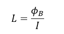
The inductance of an inductor is given as the ratio of the variable flux, also known as magnetic flux linkage, to the current that produces that flux in the circuit. This formula is given in the form
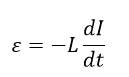
Any change in the current flowing through the inductor will produce a changing magnetic flux that causes a voltage across the inductor. Using Faraday’s law of induction, the induced emf is given by
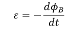
Using the above equation, we simplify this equation as
We then conclude that inductance is independent of time, current and magnetic flux linkage.
Accordingly, inductance is the quantity of electromotive force (voltage) generated for a particular rate of change of current. When the current through the inductor varies at a rate of one ampere per second, the inductor has an inductance equal to one henry producing an EMF of one volt. This is often assumed to represent the constitutive relationship of the inductor. Capacitor is the inverse of inductor. It stores energy in an electric field rather than a magnetic field. Its current-voltage relationship is established by exchanging current and voltage in the inductance equation and replacing L with capacitance C. Induction is caused by a magnetic field in the coil. The inductance of a material depends on the following fundamental entities
- The shape of the coil
- The number of turns and windings of the wire
- The cavity, present between the windings
- Permeability of the core material
- Size and dimensions of the core
In magnetic circuits, the SI unit of inductance is henry (H), which is equivalent to weber/ampere. It is represented by the letter L.
Meanwhile, an inductor cannot be confused with a capacitor. A capacitor stores energy as electrical energy while an inductor as mentioned earlier stores energy as magnetic energy. An important aspect of an inductor is that it changes polarity during discharge. In this way, the polarity of discharge can be reversed from the polarity of charge. Lenz’s law fully explains the polarity of induced voltages.
Construction of an inductor
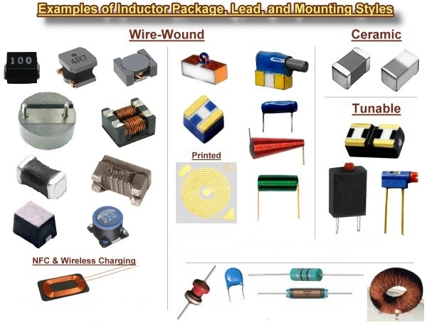
When looking at the design of an inductor, we can see that it usually consists of a coil of conductive material (usually insulated copper wire) wrapped around a core made of plastic or ferromagnetic material. One of the purposes of having a ferromagnetic core is its high permeability, which helps to generate a magnetic field while limiting it to the inductor. As a result, the inductance increases. On the other hand, low frequency inductors are usually constructed like transformers. They have electric steel laminated cores to help minimize eddy currents. “Soft” ferrite is also widely used for cores that activate at audio frequencies. Inductors come in many different sizes and shapes.
Types of an inductor
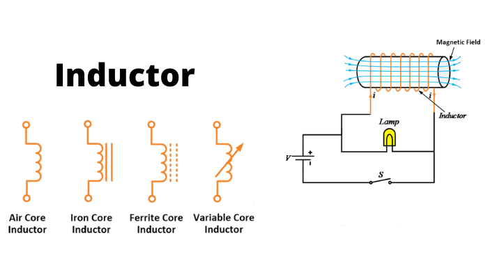
Inductor type mainly depends on the type of material used. Several materials are utilized while composing an inductor. Some of these commonly used inductors are
- Iron Core Inductor
- Air Core Inductor
- Iron Powder Inductor
- Ferrite Core Inductor (soft & hard)
Iron core inductor
The core of this type of inductor is constructed of iron, as the title indicates. These inductors have a compact design but a high power and inductance value. However, their high-frequency capability is restricted. In audio equipment, these inductors are utilized.
Air core inductor
When the quantity of inductance required is small, these inductors are chosen. There is no core loss since there is no core. However, the number of spins required for this type of inductor is more than for inductors with cores. As a result, the Quality factor is quite high. Ceramic inductors are frequently referred to as air-core inductors.
Iron powder inductor
The core of this type of inductor is Iron Oxide. They are made up of extremely thin, insulating particles of pure iron powder. Because of the air gap, it may store a lot of magnetic flux. The core of this type of inductor has very low permeability. They are frequently below 100. They are most commonly seen in switching power supply.
Ferrite core inductor
Ferrite materials are employed as the core of this type of inductor. The general formula for ferrites is XFe2O4. Where X stands for transition material. Ferrites are divided into two categories. There are soft ferrites and hard ferrites.
- Soft Ferrite: Materials that can change their polarity without the use of external energy.
- Hard Ferrite: Permanent magnets that cannot change their polarity even when the magnetic field is removed.
Choke
A choke is a type of inductor that is mostly used in electrical circuits to block high-frequency alternating current (AC). It will, however, enable DC or low-frequency signals to pass. This inductor is known as a choke because its function is to restrict fluctuations in current. This inductor is formed of an insulated wire coil coiled around a magnetic core. The core difference between chokes and other inductors is that they do not require high Q factor construction methods used to reduce resistance in inductors found in tuned circuits.
Lenz’s law
Lenz’s law states that the direction of a current induced in a circuit by a changing magnetic flux is always opposed by the magnetic field that produces it. This law qualitatively specifies the direction of the induced current.
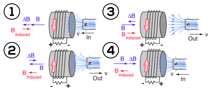
The polarity (direction) of the induced voltage is regulated by Lenz’s law. For example, if the current through the inductor increases, the induced voltage will be positive at the point of current entry and negative at the point of current exit, trying to counteract the increased current. The energy of the external circuit required to overcome this potential is stored in the magnetic field of the inductor. If the current drops, the induced voltage will be negative at the current input and positive at the current output, in order to keep the current constant. In this situation, the energy of the magnetic field is returned to the circuit. Also read here about what is the electromagnetic induction in electromagnetics?
Energy stored in an inductor
As the current flowing through the inductor changes, the magnetic field strength also changes. For example, increasing the current will increase the magnetic field. However, this is not cheap. The magnetic field includes potential energy, so increasing the field strength requires storing more energy in the field. This energy is derived from the current flowing through the inductor. The increase of the magnetic field potential is accompanied by a decrease in the potential energy of the charges circulating in the coils. As the amperage increases, it produces a voltage drop in the coils. When the current is no longer increased and kept constant, the energy in the magnetic field remains constant and no additional energy is needed, so the voltage drop across the coils disappears. Similarly, as the current through the inductor decreases, the magnetic field strength and energy in the magnetic field also decrease. This energy is returned to the circuit in the form of increased electrical potential of the moving loads, causing the voltage across the windings to increase.
The work done per unit charge on the charges flowing inside the inductor is given by –ε. The negative sign shows that the work done in reverse of the electromotive force and not the work of the electromotive force. So taking the current I through the inductor, in the count, the work done W of the charges against the electromotive force is given as
$$
\frac{d W}{d t}=-\varepsilon I
$$
From the basic conditional equation of the inductor
$$
\varepsilon=-L \frac{d I}{d t}
$$
We can extract $\mathrm{W}$
$$
\begin{gathered}
\frac{d W}{d t}=L \frac{d I}{d t} \cdot I=L I \frac{d I}{d t} \\
W=\int_0^{I_0} L_d(I) I d I
\end{gathered}
$$
Where $L_d(I)$ is called the ‘differential inductance’. And is defined as
$$
L_d=\frac{d \phi_B}{d I}
$$
In air core inductor or a ferromagnetic core inductor, this inductance is constant. So the stored energy of an inductor is
$$
\begin{gathered}
W=L \int_0^{I_0} I d I \\
W=\frac{1}{2} L I_0^2
\end{gathered}
$$
This equation is only valid for linear regions of the magnetic flux, at currents below saturation level of the inductor, where the inductance is approximately constant.
Voltage step response
When an inductor is introduced to a voltage supply, its short and long term responses can be calculated easily.
– In the short-time limit, since the current do not change continuously therefore, the current at initial instant is zero. The short-time equivalence of an inductor is an open circuit.
– In the long-time limit, the transient response of inductor is absent, causing the magnetic flux through the conductor constant, so no voltage is induced between the terminals of the inductor. Therefore, the long-time equivalence of an inductor is a short circuit.
Ideal and real inductor
The structural equation describes the operation of a perfect inductor of inductance L and without resistance, capacitance or energy loss. In practice, the inductor does not behave like this theoretical model. A true inductor has a large resistance due to the resistance of the conductor and the loss of energy in the core, and a parasitic capacitance due to the potential difference between the turns of the wire. The capacitive resistance of the real inductor increases with frequency and at a certain frequency the inductor behaves like a resonant circuit. Above this self-resonant frequency, reactance prevails over the impedance of the inductor. Due to the skin effect and proximity effect, the resistance loss in the coil increases at high frequencies. Due to core hysteresis and eddy currents, ferromagnetic core inductors suffer additional energy losses that increase with frequency.
Magnetic core inductors strongly deviate from ideal operation at high currents due to the nonlinearity caused by core saturation. Inductors can radiate electromagnetic energy to the environment and can absorb electromagnetic emissions from other circuits, causing electromagnetic interference. A saturation reactor is an early solid-state power amplifier and switching device that uses core saturation to stop the passage of induced current through the core.
Q factor
DCR (DC resistance) refers to winding resistance, which appears as resistance in series with inductance. Part of the reactive energy is dissipated through this resistor. The quality factor (or Q) of an inductor is the ratio of its inductive reactance to its resistance at a given frequency, and is a measure of its efficiency.
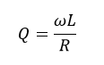
Where L is the inductance, R is the resistance in DC and the product of is the inductive reactance.
The higher the Q-factor of an inductor, the more it behaves like an ideal inductor. Radio transmitters and receivers use High-Q inductors with capacitors to form resonant circuits. On the other hand, as the Q increases, the bandwidth of the resonant circuit decreases, causing losses with increasing frequency. Core materials are selected for optimum performance in the frequency band. A High-Q inductor should avoid saturation, which can be achieved by using a (physically larger) air-core inductor. Air cores may be used at frequencies above VHF. A properly designed air core inductor can have a Q in the thousands.
Applications of Inductor
Inductors are widely used in analog circuits and signal processing. Use a large inductor in the power supply to suppress ripple at many times the line frequency (switching frequency for switching power) of the DC output and install a small inductor ferrite or O-ring cable to avoid ripple. Radio interference is transmitted over cables. Many switching power supplies use inductors as energy storage to generate DC current. The inductor powers the circuit to maintain current during the “off” switching, allowing the terrain to have an output voltage higher than the input voltage. An oscillating circuit consisting of an inductor connected in series with a capacitor acts as a resonant for the oscillating current. Tuning circuits are commonly found in radio frequency equipment such as radio transmitters and receivers, narrow band pass filters to select a single frequency from the composite signal, and electronic oscillators to generate a sine wave. Inductors are also used in electrical networks to reduce switching and fault currents. They are often referred to as field nuclear reactors.
Inductors in parallel
As we are familiar with the parallel circuitry, the current in the parallel circuit changes whereas the voltage remains constant. By using basic analysis of parallel circuit
$$
I_t=I_1+I_2+\cdots+I_n
$$
The voltage across the inductor is given by
$$
V=L \frac{d I}{d t}
$$
We can simplify it further as
$$
\begin{gathered}
V=L_t * \frac{d I_t}{d t} \\
V=L_t * \frac{d\left(I_1+I_2+\cdots+I_n\right)}{d t} \\
V=L_t * \frac{d I_1}{d t}+L_t * \frac{d I_2}{d t}+\cdots+L_t * \frac{d I_n}{d t}
\end{gathered}
$$
Thus
$$
V=L_t *\left(\frac{V}{L_1}+\frac{V}{L_2}+\cdots+\frac{V}{L_n}\right)
$$
After simplifying as voltage is constant throughout
$$
\frac{1}{L_t}=\frac{1}{L_1}+\frac{1}{L_2}+\cdots+\frac{1}{L_n}
$$
Inductors in series
As in the series circuitry, the current remains constant throughout whereas the voltage changes at each terminal of the inductor thus
$$
V_t=V_1+V_2+\cdots+V_n
$$
The voltage across inductor is given by
$$
V=L \frac{d I}{d t}
$$
Simplifying it further
$$
L_t * \frac{d I}{d t}=L_1 * \frac{d I_1}{d t}+L_2 * \frac{d I_2}{d t}+\cdots+L_n * \frac{d I_n}{d t}
$$
But
$$
I=I_1=I_2=\cdots=I_n
$$
Therefore
$$
L * \frac{d I}{d t}=L_1 * \frac{d I}{d t}+L_2 * \frac{d I}{d t}+\cdots+L_n * \frac{d I}{d t}
$$
$$
L_t=L_1+L_2+\cdots+L_n
$$
Also read here: