Table of Contents
Introduction
The printed circularly polarized half-moon antenna is a small and lightweight device that is commonly used in situations where size and weight are important factors. It is designed to work with circular polarization, making it an excellent choice for communication and navigation systems that require coverage in all directions. The antenna’s versatility lies in its ability to be easily printed onto circuit boards or flexible substrates to meet the specific needs of various applications.
What is Monopole Antenna?
In the world of wireless communications, antennas play a crucial role in transmitting and receiving electromagnetic signals. There are various types of antennas, each with its own advantages and disadvantages.
One type of antenna that has gained attention in recent years is the printed circularly polarized half-moon monopole antenna. Printed circularly polarized antennas are becoming increasingly popular due to their ability to suppress multipath interference and reduce polarization mismatch. These antennas offer several advantages over other types of antennas, including compact size, low profile, simple design, and cost-effectiveness.
Fundamentals of Circularly Polarized Antennas
Circularly polarized antennas are advantageous in wireless systems due to their ability to generate and receive signals at arbitrary polarization angles and reduce multipath interference. They can endure bad weather conditions, mitigate path loss and Faraday rotation, and prevent polarization mismatch.
Circularly polarized antennas are used in various communication systems, including satellite, wireless, and radar systems.
- They are designed to transmit and receive electromagnetic waves that are circularly polarized.
- Circularly polarized waves have a twisting, helical motion that enables them to propagate in a specific direction without being affected by other signals or noise.
- The two types of circular polarization are right-hand circular polarization (RHCP) and left-hand circular polarization (LHCP).
- RHCP waves rotate clockwise when viewed in the direction of propagation, while LHCP waves rotate counterclockwise.
- Both RHCP and LHCP waves are used in circularly polarized antennas.
- One common type of circularly polarized antenna is the helical antenna, which consists of a wire that is wound in the shape of a helix.
- Helical antennas are used in applications such as GPS systems and satellite communication systems.
- Another type of circularly polarized antenna is the patch antenna, which consists of a flat metal patch on a ground plane.
- Patch antennas are used in applications such as WLAN and cellular communication systems.
- Circularly polarized antennas offer advantages over linearly polarized antennas in terms of signal quality, signal isolation, and noise rejection.
- However, circularly polarized antennas are generally more complex to design and manufacture than linearly polarized antennas
These innovative antennas offer unique advantages, making them valuable for various applications in wireless communication and remote sensing. In this report, we explore their introduction, advantages, and potential applications.
Applications
Printed circularly polarized half moon antennas find applications in various fields, including:
- These antennas are used in Wi-Fi, Bluetooth, and other wireless communication systems to improve signal reception and reduce polarization-related signal degradation.
- In radio-frequency identification (RFID) systems, these antennas enhance tag detection and data transfer reliability.
- Remote Sensing: The omnidirectional radiation pattern and circular polarization of these antennas make them suitable for satellite communication and Earth observation systems.
- Due to their compact and lightweight design, these antennas can be integrated into UAVs for communication and remote sensing applications.
- In automotive radar systems, circular polarization is valuable for detecting objects from various angles and in different weather conditions.
Methodology
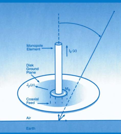
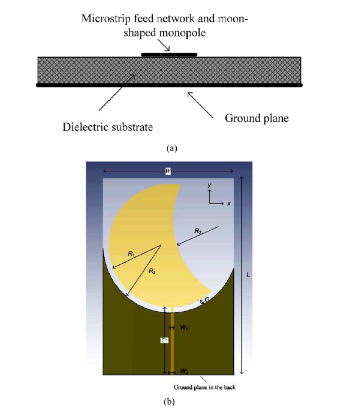
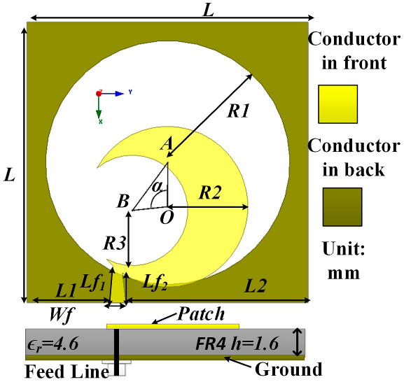
The authors that wrote the research papers analyzed and begin by designing the monopole element. They use a parametric analysis to determine the optimal dimensions of the monopole element for the desired frequency range. The monopole element is designed to be a half-moon shape to achieve circular polarization.
Once the monopole element is designed, the authors then design the ground plane. The ground plane is designed to be slightly larger than the monopole element to provide adequate radiation resistance. The ground plane is also designed to be triangular-shaped to improve the antenna’s performance.
To achieve circular polarization, the authors employ two techniques. First, they locate the monopole element asymmetrically on the ground plane. This asymmetry creates a phase difference between the two orthogonal components of the radiated field, resulting in circular polarization. Second, the authors adjust the size of the ground plane to fine-tune the phase difference between the two orthogonal components of the radiated field.
Once the monopole element and ground plane are designed, the authors then fabricate the antenna using a printed circuit board (PCB) process. The PCB process allows for the rapid and low-cost fabrication of the antenna.
Future work
The authors suggest that future work could focus on improving the antenna’s bandwidth and efficiency. They also suggest that the antenna could be integrated with other components, such as filters and amplifiers, to create a complete system.
One way to improve the antenna’s bandwidth would be to use a multi-resonant design. A multi-resonant design would allow the antenna to resonate at multiple frequencies, thereby increasing the antenna’s bandwidth. Another way to improve the antenna’s bandwidth would be to use a metamaterial substrate. A metamaterial substrate is a material that has artificially engineered electromagnetic properties. Metamaterial substrates can be used to improve the antenna’s bandwidth and efficiency.
To improve the antenna’s efficiency, the authors could use a higher quality PCB material. They could also use a lossless matching network to match the antenna’s impedance to the impedance of the feed line.
The authors could also integrate the antenna with other components, such as filters and amplifiers, to create a complete system. For example, they could integrate the antenna with a filter to select a specific frequency band. Or, they could integrate the antenna with an amplifier to boost the antenna’s transmit power.
Conclusion
The authors conclude that their proposed antenna has a simple design, low cost, and good performance. They believe that the antenna has the potential to be used in a variety of wireless applications, such as wireless local area networks (WLANs) and radio frequency identification (RFID) systems.
The proposed antenna has a number of advantages over other types of CP antennas. First, the antenna is simple to design and fabricate. Second, the antenna is low cost. Third, the antenna has good performance in terms of bandwidth, efficiency, and radiation pattern.
The proposed antenna has the potential to be used in a variety of wireless applications, such as WLANs, RFID systems, and satellite communications systems.