Introduction to Clamper Circuits
What are the Clamper Circuits? Types of Clampers. Clampers are also known as the DC level restorers. Clampers are used for adding a positive or negative DC voltage levels to the input voltage waveform. Clampers do not change the shape of input voltages as well as the peak-to-peak voltages of input waveform.
Clamper circuits are electronic circuits used to shift the DC level of a waveform without altering its shape. They are commonly used to establish a reference voltage or to “clamp” the waveform to a desired DC level. Clamper circuits typically consist of a diode, a capacitor, and a resistor.
The diode in a clamper circuit allows current to flow in only one direction, either charging or discharging the capacitor depending on the polarity of the input waveform. The capacitor stores charge and helps to establish the desired DC level. The resistor is used to control the charging or discharging time of the capacitor.
Working of Clampers
Types of Clamper Circuits
There are two types of clamper circuits:
- Positive clamper
- Negative clamper
In a positive clamper, the capacitor charges through the diode during the positive half-cycle of the input waveform, shifting the waveform upwards. In a negative clamper, the capacitor charges during the negative half-cycle, shifting the waveform downwards.
Clamper circuits are often used in applications such as video signal processing, audio signal conditioning, and waveform shaping in communication systems. They are valuable tools for manipulating and adjusting the DC level of waveforms while preserving their original shape.
Working of Positive Clamper Circuits
Analysis of Clamper Circuits
There are certain points, that you must always keep in mind for analyzing the operation of clamper circuits. These are discussed below:
- Start the analysis with that portion of input waveform for which diode will be forward biased.
- In order to meet the criteria mentioned in part 1, you may skip one portion of the input waveform initially.
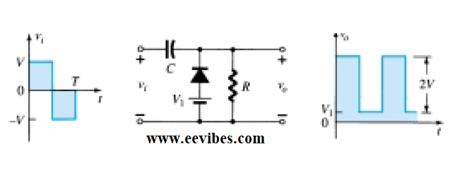
- Capacitor will charge to the peak value of input voltage via diode, when it will be forward biased.
- When the diode will be reverse biased, the capacitor should retain its voltages in order to make sure the effective clamping action.
- This can be done if the discharging time of the capacitor is equal to the 10 times the time period of input waveform.
Example of Clamper Circuits
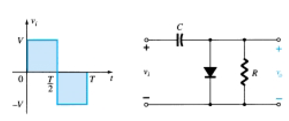
The following figure shows an example of clamper circuit. In this circuit, Vin represents the input waveform, Vout is the output waveform, and GND represents the ground reference. The components are as follows:
R: Resistor
D: Diode
C: Capacitor
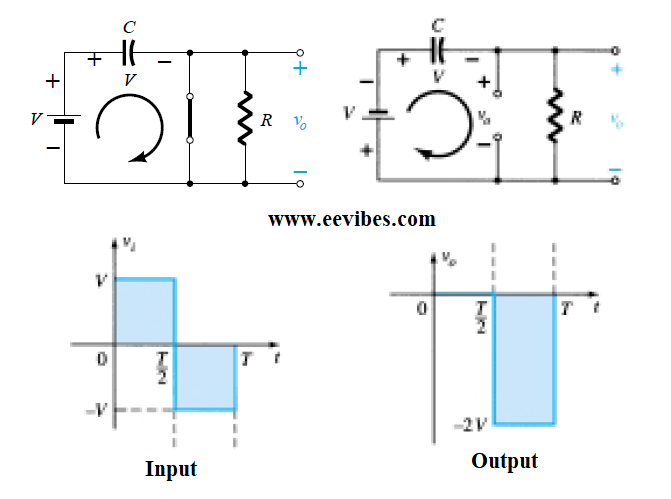
During the positive half-cycle of the input waveform, the diode conducts and charges the capacitor C through the resistor R. This causes the voltage across the capacitor to increase, shifting the waveform upwards. During the negative half-cycle, the diode blocks current flow, and the capacitor holds the charge, maintaining the shifted DC level.
The output waveform Vout will be the input waveform Vin shifted upwards by the voltage across the capacitor. The values of the resistor and capacitor, as well as the characteristics of the input waveform, determine the degree of shifting.
Note that this is a simplified example, and in practical circuits, additional components such as coupling capacitors or voltage sources may be included to achieve desired functionality or improve performance.
Also read here:
What are the Clipper Circuits or Voltage Limiters?