Introduction to Voltage Clippers or Voltage Limiters
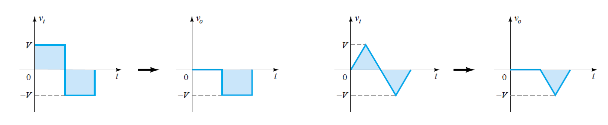
The voltage limiters are also named as voltage clipper circuits. They find their application where the load requirement is less than the source voltages. These circuits can clip-off the portion of input voltages without disturbing the remaining part of input signal. The half wave rectifier is the simplest form of diode clipper where either the positive or negative portion of input voltages is clipped-off. There is no limitation for the types of the signals that we can apply to the clipper circuits.
Working of Clipper Circuits
Types of Clipper Circuits
We can classify the diode clipper circuits into two categories:
- Series Clippers
- and Parallel clippers.
These clipper circuits then can be unbiased or biased depending on either there is some battery is connected or not in series with the diode.
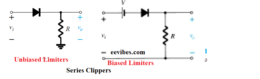
Series Clippers
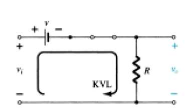
In this circuit the diode is connected in series with the load. The biased and unbiased series configuration is shown in the figure below.
Analysis of Series Clippers
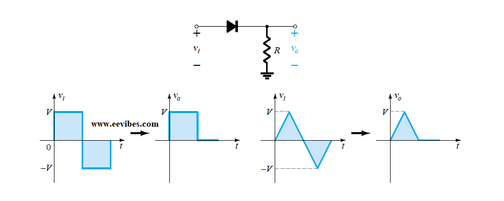
For the analysis of the series clippers, we will notice when diode is forward biased and when it is reverse biased. When the diode will be forward biased, we will replace it with short circuit (in case of ideal diode) and with 0.7V battery in case of practical diode model.
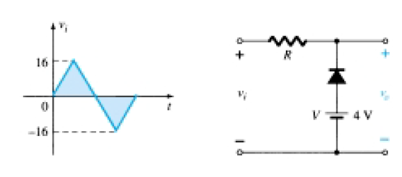
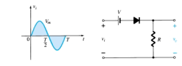
Clipper Circuit Example
Consider the following circuit. In this circuit, a battery is connected in series with the diode and voltage source. This battery will add negative DC Offset voltages in the ac signal and then we will see when diode will be forward or reverse biased.
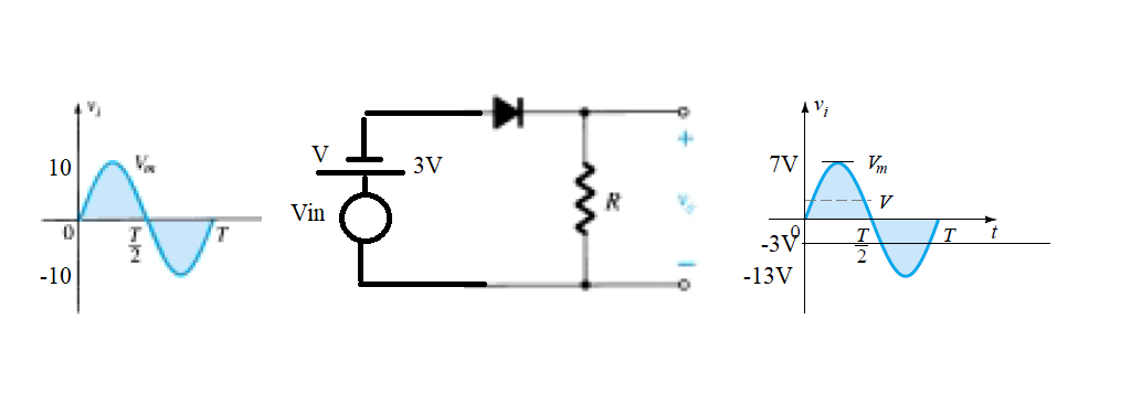
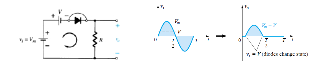
Now as long as input voltages at the cathode are negative (-3v), it will remain reverse biased. In this condition, we can replace it with an open circuit and no current will flow through the resistor. Hence according to ohm’s law voltage drop across the load will be zero. When the voltages will reach to 0.7V at input side it will be forward biased and hence the current will flow through the circuit resulting in voltage drop across the resistor. The equivalent circuit and output voltage waveform is shown in the figure below.
Working of Series Clippers/Limiters
Parallel Clipper Circuits
In parallel clipper circuits, the load and diode both are connected in parallel with each other. The following figure shows the response of of parallel clipper circuits.
Example of Parallel Clipper Circuits

Working of Parallel Clippers/Limiters
Application of Diode Clippers
Many circuits have certain restrictions on the input level to avoid damaging the circuit. For example, almost all digital circuits should not have an input level that exceeds the power supply voltage. An input of a few volts more than this could damage the circuit. To prevent the input from exceeding a specific level, you may see a diode limiter across the input signal path in many digital circuits.
Also read here:
What are the Clamper Circuits? Types of Clampers
Diode as a Non-Linear Device: Ideal Diode Current Equation