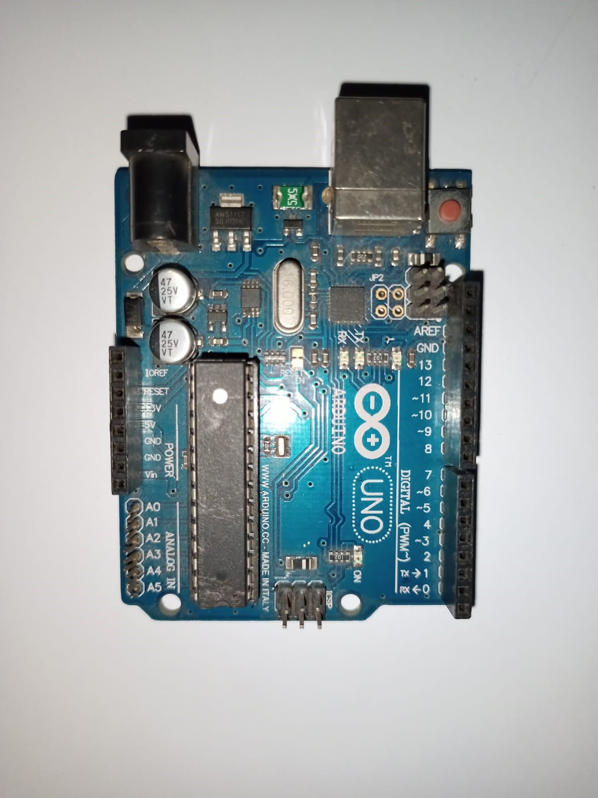
What is Arduino UNO?
How to Show Display on Dot Matrix using Arduino? Arduino Uno is an open-source microcontroller board based on the ATmega328P microcontroller. It is one of the most popular boards in the Arduino family and is widely used in the field of electronics, robotics, and prototyping. The Arduino Uno board provides a simple and accessible platform for both beginners and advanced users to create interactive electronic projects.
Features and Uses:
-
Microcontroller:
Arduino Uno is built around the ATmega328P microcontroller, which runs at a clock speed of 16 MHz and has 32KB of flash memory for program storage. It also has 2KB of SRAM and 1KB of EEPROM.
-
Digital and Analog I/O:
Arduino Uno has a total of 14 digital input/output pins, where 6 can be used as PWM (Pulse Width Modulation) outputs. Additionally, it has 6 analog input pins, allowing you to read analog sensor values.
-
Programming:
Arduino Uno can be programmed using the Arduino programming language, which is based on Wiring. The programming environment is user-friendly and easy to learn, making it accessible to beginners. You can write code on your computer and upload it to the board using a USB cable.
-
Shields and Modules:
Arduino Uno is compatible with various expansion boards called shields, which allow you to add functionalities such as Wi-Fi, Bluetooth, motor control, and more. There is a wide range of shields available, making it versatile for different projects.
-
Educational Tool:
Arduino Uno is extensively used in educational settings to teach programming, electronics, and robotics. Its simplicity and flexibility make it suitable for beginners to grasp the fundamentals of electronics and coding.
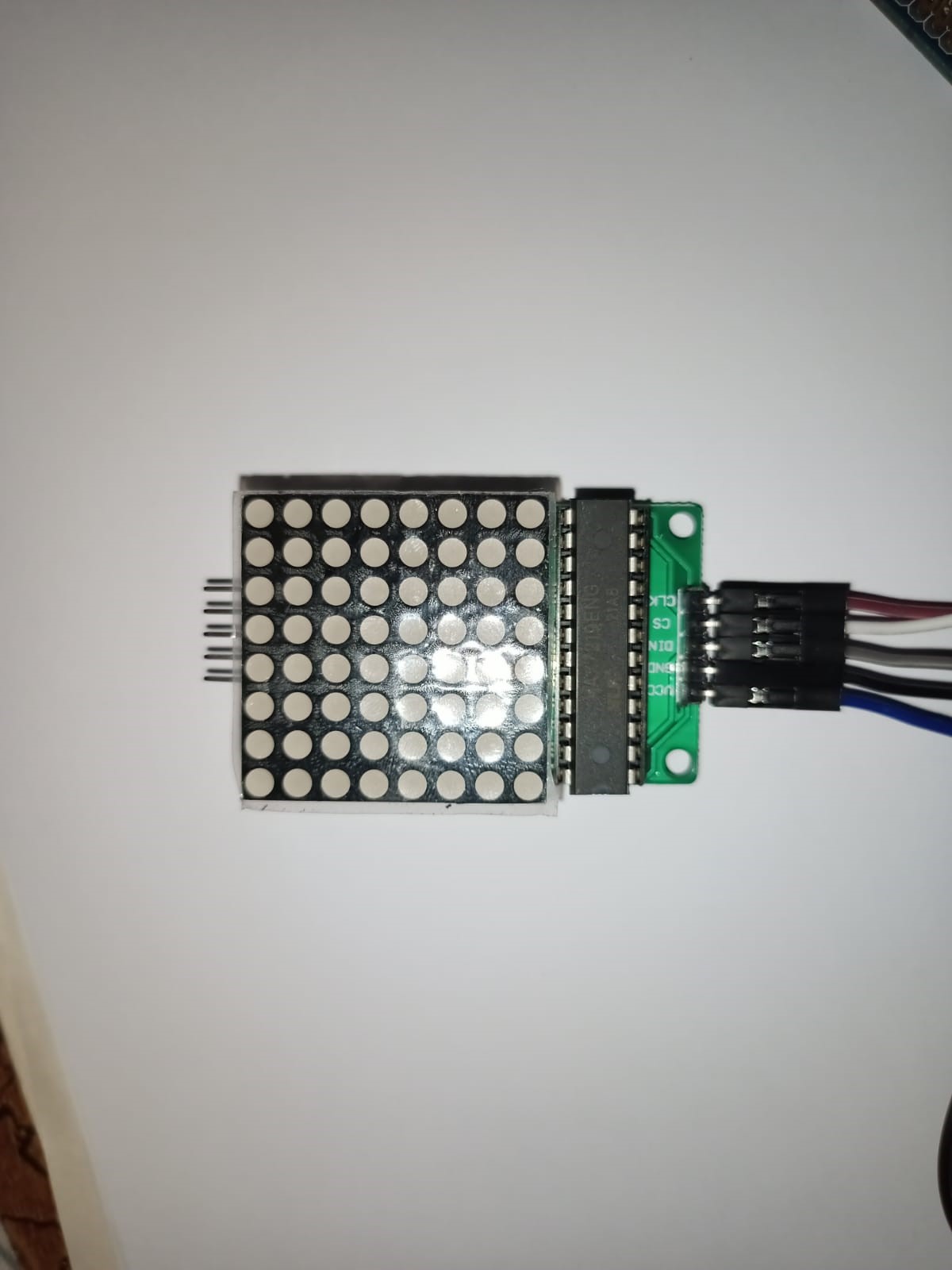
What is Dot Matrix?
A dot matrix is a display technology that uses an array of small, individual dots to form characters, symbols, or images. These dots are usually light-emitting diodes (LEDs) or pixels on a screen. The dots are arranged in a grid pattern, and each dot can be turned on or off independently.
Principle:
Dot matrix displays work on the principle of combining multiple dots to form visual information. By controlling the state of each dot, you can create patterns, characters, and graphics on the display.
Features and Uses:
-
Alphanumeric Displays:
Dot matrix displays can show alphanumeric characters, including letters, numbers, and symbols. These displays are often used in digital clocks, scoreboards, and information panels where text-based information needs to be displayed.
-
Pixel-Based Graphics:
Dot matrix displays can also create simple graphics and images. By controlling the dots individually, you can form basic shapes, icons, or even simple animations. This makes them suitable for applications like gaming devices, portable calculators, and small information displays.
-
Scrolling and Animation:
Dot matrix displays can be programmed to show scrolling text or animated patterns. This feature is often used in message boards, information tickers, and public transportation displays to convey dynamic information.
-
Communication and Signage:
Dot matrix displays are frequently used for communication and signage purposes. They can be found in train stations, airports, bus stops, and other public places to display arrival and departure times, announcements, or directions.
-
Educational Tools:
Dot matrix displays are valuable educational tools for teaching concepts like pixel-based graphics, digital electronics, and programming. They allow students to understand the relationship between individual dots and the overall display, fostering learning in technology and design fields.
Arduino and Dot Matrix:
Arduino can be used to control a dot matrix display and create various visual outputs. Here’s how you can use Arduino with a dot matrix display:
-
Hardware Setup:
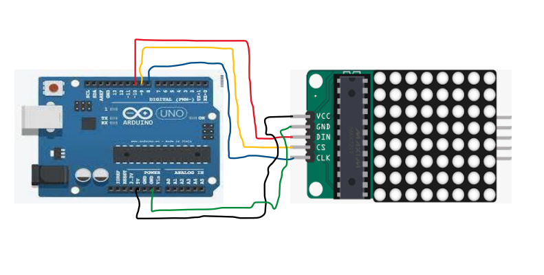
Connect the dot matrix display to the Arduino Uno board. Typically, dot matrix displays have two sets of pins: one for the rows and another for the columns. Connect the row pins to the digital output pins of the Arduino and the column pins to the digital input pins.
-
Library Installation:
To simplify the programming process, you can use a library specifically designed for dot matrix displays. One popular library is the “LedControl” library. Install this library in the Arduino IDE by going to “Sketch” -> “Include Library” -> “Manage Libraries” and search for “LedControl”. Install and import the library into your project.
-
Code Implementation:
Write Arduino code to control the dot matrix display. Use the functions and methods provided by the LedControl library to control the individual LEDs or pixels of the dot matrix display. You can set the state (on/off) of each LED to form characters, symbols, or graphics on the display.
-
Upload and Run:
Connect the Arduino board to your computer using a USB cable. Compile the code in the Arduino IDE and upload it to the Arduino board. The Arduino will execute the code and control the dot matrix display accordingly.
Connection of DOT Matrix with Arduino
Code:
#include <LedControl.h>
int DIN = 10;
int CS = 9;
int CLK = 8;
LedControl lc=LedControl(DIN,CLK,CS,0);
void setup(){
lc.shutdown(0,false);
lc.setIntensity(0,15); //Adjust the brightness maximum is 15
lc.clearDisplay(0);
}
void loop(){
//Facial Expression
byte smile[8]= {0x3C,0x42,0xA5,0x81,0xA5,0x99,0x42,0x3C};
byte neutral[8]= {0x3C,0x42,0xA5,0x81,0xBD,0x81,0x42,0x3C};
byte sad[8]= {0x3C,0x42,0xA5,0x81,0x99,0xA5,0x42,0x3C};
//Facial Expression
printByte(smile);
delay(1000);
printByte(neutral);
delay(1000);
printByte(sad);
delay(1000);
}
void printByte(byte character [])
{
int i = 0;
for(i=0;i<8;i++)
{
lc.setRow(0,i,character[i]);
}
}
Note: Must use ledcontrol.h library in the code
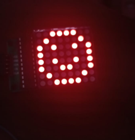
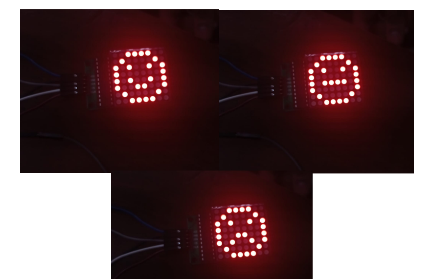
Output:
Explanation:
This code is written in Arduino language and uses the LedControl library to control 8×8 LED matrix display. Let’s go through the code step by step:
- The #include <LedControl.h> statement at the beginning of the code includes the LedControl library, which provides functions to control LED matrix displays.
- The next few lines declare and initialize variables DIN, CS, and CLK with the pin numbers to which the LED matrix display is connected. These variables will be used to configure the LedControl object later.
- The line LedControl lc = LedControl(DIN, CLK, CS, 0); creates an instance of the LedControl class named ‘lc’ and initializes it with the pin numbers.
- The ‘setup()’ function is a special function in Arduino that is executed once when the board is powered on or reset. In this code, the ‘setup()’ function performs the following actions:
- ‘lc.shutdown(0, false); disables the shutdown mode of the LED matrix display at address 0, allowing it to operate.
- ‘lc.setIntensity(0, 15); sets the intensity (brightness) of the LED matrix display at address 0 to the maximum value of 15.
- ‘lc.clearDisplay(0); clears the LED matrix display at address 0 by turning off all LEDs.
- The loop() function is another special function in Arduino that is executed repeatedly after the setup() In this code, the loop() function does the following:
- Defines three arrays smile, neutral, and sad, each representing a pattern for a facial expression on the LED matrix display. Each array element contains a byte representing a row of LEDs.
- Calls the printByte() function with the smile array as an argument, which displays the smiley face pattern on the LED matrix display.
- Delays the program execution for 1 second using the delay(1000) function.
- Calls printByte() function with the neutral array as an argument, which displays the neutral face pattern.
- Delays again for 1 second.
- Calls printByte() function with the sad array as an argument, which displays the sad face pattern.
- Delays again for 1 second.
- This loop continues indefinitely, displaying the three facial expressions repeatedly.
- The printByte() function is a custom function defined in this code. It takes a byte array character[] as an argument, which represents a row of LED states. The function uses a loop to iterate over the elements of the array and sets the corresponding row of LEDs on the LED matrix display using the setRow() function.
Overall, this code controls an 8×8 LED matrix display to show three different facial expressions (smile, neutral, and sad) repeatedly with a 1-second delay between each expression.
Conclusion:
In conclusion, the Arduino Uno is an open-source microcontroller board based on the ATmega328P microcontroller. It offers a simple and accessible platform for creating interactive electronic projects, making it popular in the fields of electronics, robotics, and prototyping. The board features a 16 MHz ATmega328P microcontroller with 32KB of flash memory, 2KB of SRAM, and 1KB of EEPROM. It provides a range of digital and analog I/O pins for connecting various components and sensors. Arduino Uno can be programmed using the Arduino language and offers compatibility with a wide range of shields and modules for expanding its functionalities. It serves as an educational tool for teaching programming, electronics, and robotics due to its simplicity and flexibility.
On the other hand, a dot matrix is a display technology that utilizes a grid pattern of small individual dots, typically light-emitting diodes (LEDs) or pixels, to form characters, symbols, or images. By controlling the state of each dot, patterns, characters, and graphics can be created. Dot matrix displays are commonly used for alphanumeric displays, pixel-based graphics, scrolling text, animations, communication signage, and as educational tools for teaching pixel-based graphics, digital electronics, and programming.
In this code, an Arduino Uno board is used in conjunction with the LedControl library to control an 8×8 LED matrix display. The code displays three different facial expressions (smile, neutral, and sad) on the LED matrix display, with each expression shown for a duration of 1 second. The printByte() function is responsible for setting the LED states based on the predefined byte arrays representing the facial expression patterns.
Overall, the code demonstrates how Arduino and dot matrix displays can be combined to create visual outputs, showcasing the versatility and potential of these technologies in various applications.
Also check
How to control the speed and direction of DC motor using Arduino?
Arduino Project: How to control the speed of DC motor?
How to control the speed of DC motor using PWM ?