How to control the speed and direction of DC motor using Arduino? In this project, we are going to use a very popular motor driver IC called an L293D. The advantage of using this chip is that we can control two motors at the same time, as well as control their direction. There is also a pin-for-pin compatible chip available known as the SN754410, which can also be used and has a higher current rating. The IC has its own internal diodes, so we do not need one for this project.
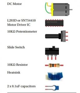
Components required
Description:
Arduino UNO: It is a microcontroller board based on the ATmega328P. It has 14 digital input/output pins (of which 6 can be used as PWM outputs), 6 analog inputs, a USB connection, a power jack, an ICSP header and a reset button. It contains everything needed to support the microcontroller.

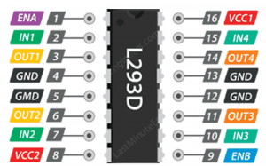
L293D Motor Driver IC:
The L293D is a dual-channel H-Bridge motor driver capable of controlling two motors and their direction at a same time. The L293D has the advantage of being tiny and having all those transistors and diodes packaged up inside a small space.
Capacitor:
It is a device that stores electrical energy in an electric field. It is a passive electronic component with two terminals.
Resistor:
It is used to reduce current flow, adjust signal levels, to divide voltages, bias active elements, and terminate transmission lines, among other uses.
Potentiometer:
It is commonly used to control electrical devices such as volume controls on audio equipment. Potentiometers operated by a mechanism can be used as position transducers.
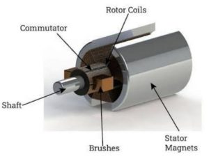
DC motor:
It is any of a class of rotary electrical motors that converts direct current (DC) electrical energy into mechanical energy. The most common types rely on the forces produced by magnetic fields.
Controlling a DC Motor
In order to have a complete control over DC motor, we have to control its speed and rotation direction. This can be achieved by combining these two techniques.
- PWM– For controlling speed
- H-Bridge– For controlling rotation direction
PWM
For controlling speed
The speed of a DC motor can be controlled by varying its input voltage. A common technique for doing this is to use PWM (Pulse Width Modulation). PWM is a technique where average value of the input voltage is adjusted by sending a series of ON-OFF pulses.
“The average voltage is proportional to the width of the pulses known as Duty
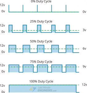
The higher the duty cycle, the greater the average voltage being applied to the dc motor (High Speed) and the lower the duty cycle, the less the average voltage being applied to the dc motor (Low Speed). Below image illustrates PWM technique with various duty cycles and average voltages.
Speed Control Pins
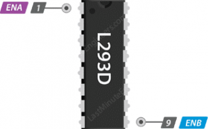
The speed control pins viz. ENA and ENB are used to turn ON, OFF and control speed of motor A and motor B respectively. Pulling these pins HIGH will make the motors spin, pulling it LOW will make them stop. But, with Pulse Width Modulation (PWM), we can actually control the speed of the motors.
H-Bridge – For controlling rotation direction
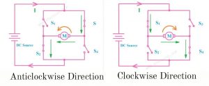
The DC motor’s spinning direction can be controlled by changing polarity of its input voltage. A common technique for doing this is to use an H-Bridge. An H-Bridge circuit contains four switches with the motor at the center forming an H-like arrangement. Closing two particular switches at the same time reverses the polarity of the voltage applied to the motor. This causes change in spinning direction of the motor. Below animation illustrates H-Bridge circuit working.
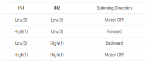
Direction Control Pins
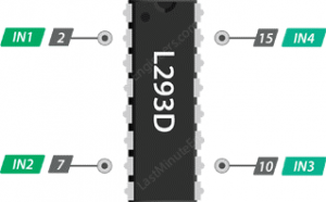
Using the direction control pins, we can control whether the motor spins forward or backward. These pins actually control the switches of the H-Bridge circuit inside L293D IC. The IC has two direction control pins for each channel. The IN1,IN2 pins control the spinning direction of the motor A while IN3,IN4 control motor B. The spinning direction of a motor can be controlled by applying either a logic HIGH (5 Volts) or logic LOW (Ground) to these pins. The below chart illustrates how this is done.
Circuit Diagram Using Arduino UNO
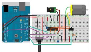
- Start by connecting power supply to the motor. It is rated for 3 to 9V. So, we will connect external 9V power supply to the Vcc2 pin.
- A potentiometer is connected to the analogue input A0, as shown in the diagram below (we will pick an output value between 1-12 volts with this potentiometer).
- Next, we need to supply 5 Volts for the L293D’s logic circuitry. Connect Vcc1 pin to 5V output on Arduino. Make sure you common all the grounds in the circuit.
- Now, the input and enable pins (ENA, IN1, IN2, IN3, IN4 and ENB) of the L293D IC are connected to six Arduino digital output pins (9, 8, 7, 5, 4 and 3). Note that the Arduino output pins 9 and 3 are both PWM-enabled.
- Finally, connect one motor to across OUT1 & OUT2 and the other motor across OUT3 & OUT4. You can interchange your motor’s connections, technically, there is no right or wrong way.
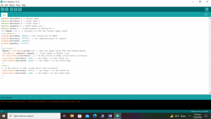
Arduino Code for DC motor speed and direction control
#define switchPin 2 // switch input
#define motorPin1 3 // L293D Input 1
#define motorPin2 4 // L293D Input 2
#define speedPin 9 // L293D enable pin 1
#define potPin 0 // Potentiometer on analog Pin 0
int Mspeed = 0; // a variable to hold the current speed value
void setup()
{
pinMode(switchPin, INPUT); //set switch pin as INPUT
pinMode(motorPin1, OUTPUT); // set remaining pins as outputs
pinMode(motorPin2, OUTPUT);
pinMode(speedPin, OUTPUT);
}
void loop()
{
Mspeed = analogRead(potPin)/4; // read the speed value from the potentiometer
analogWrite (speedPin, Mspeed); // write speed to Enable 1 pin
if (digitalRead(switchPin))
{
// If the switch is HIGH, rotate motor clockwise
digitalWrite(motorPin1, LOW); // set Input 1 of the L293D low
digitalWrite(motorPin2, HIGH); // set Input 2 of the L293D high
}
else
{
// if the switch is LOW, rotate motor anti-clockwise
digitalWrite(motorPin1, HIGH); // set Input 1 of the L293D low
digitalWrite(motorPin2, LOW); // set Input 2 of the L293D high
}
}
Conclusion:
In this project we have used the popular L293D motor driver IC instead of making our own H-bridge out of transistors and diodes, no doubt it would do the same job as the L293D. But, in this project we can see that the L293D has the advantage of being tiny and having all those transistors and diodes packaged up inside a small space. The L293D is a dual-channel H-Bridge motor driver capable of controlling two motors and their direction at a same time. Moreover, from this project we also know how to use an H-bridge to change the direction of a motor.
How to control the speed and direction of DC motor using Arduino Video?
https://www.youtube.com/watch?v=HhpOLGuLo38
Other Projects
- How to Display on 8×8 Dot Matrix LED Using Arduino(UNO)?
- How to Design RGB Mood Lamp using Arduino?
- Serial Temperature Sensor Project using Arduino
- How to design an LED Flasher on Arduino Board
- Design of Traffic Light Control system using Arduino
- Arduino Project: How to control the speed of DC motor?
- Arduino Project: Send Command with Serial Communication
- Arduino Project: LED Fire Effect