Table of Contents
Overview
How to Display on 8×8 Dot Matrix LED Using Arduino(UNO). In this project, we will learn how to use 8×8 dot matrix LED module with Arduino. At the end, you’ll be able to display any shape or text on one or more Dot matrix easily, fixed or scrolled, using Arduino.
Objectives
- What is dot matrix LED
- How to use Dot matrix LEDs with Arduino
- Displaying specific shapes on a Dot matrix LED module
- Cascading two Dot matrix LEDs
What Is Dot Matrix?
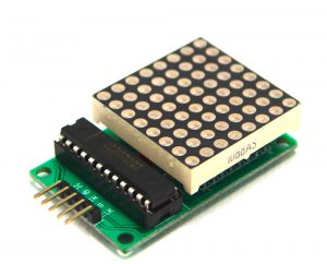
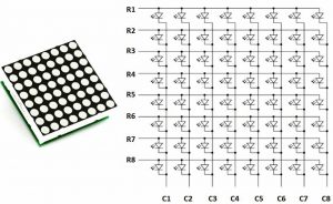
A dot matrix LED is simple an array of large number of LEDs together on we can display whatever we want such as certain numbers, pattern and shapes by just blinking LED according to certain pattern. IN a Dot Matrix LED the number of matrices are determined by simply the number of columns and rows in that matrix. Although the dot matrix LED comes in different type but the most common and one which we are using in this project is dot matrix LED 8×8 which have 64 matrix mean 8 rows and 8 columns. In order to connect dot matrix LED with circuit we simply connects all the rows and columns with the digital pins which give us 16 connection in case of 8×8 dot matrix but this is wrong way of connection. In general a module called MAX72xx ICS are used for dot matrix LED circuit connection the benefit of doing this that we need to connect to 4 digital pins instead of 16. You can also connect multiple Dot Matrix (up to 8) to each other without needing any extra pin and cascades them.
Connection of Circuit?
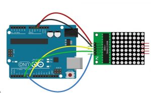
In order to display certain pattern or shapes on dot matrix LED we simple connect it with the Arduino board the connections are so simple.
- First of connect the Vcc pin of matrix with the 5v pin of Arduino
- Now connect the GND pin of both Arduino and dot matrix together
In the last connect Din and CLK pin of dot matrix with any of the digital pin of Arduino board.
Code for DOT Matrix display using Arduino
Now here we are going to write the cod for dot matrix on Arduino for this purpose first we have to install the libraries for dot matrix .There are various libraries for Dot matrix and Arduino. The Ledcontrol and MaxMatrixlibraries are two of the most common libraries, both have the same structure and we are using the in our project
#include <MaxMatrix.h>
int DIN = 7;
int CLK = 6;
int CS = 5;
int maxInUse = 1;
byte buffer[20];
char text[] = “a”;
MaxMatrix m(DIN, CS, CLK, maxInUse);
void setup()
{
m.init();
m.setIntensity(8);
}
void loop()
{
m.setDot(0, 7, true);
m.setDot(0, 7, true);
delay(1000);
m.setDot(7, 0, true);
delay(1000);
m.setColumn(3, B11110000);
delay(1000);
m.setColumn(4, B00001111);
delay(1000);
m.clear();
delay(1000);
}
Display of Shape on Dot Matrix
In order to display a certain shape on our dot matrix we simply connect the Arduino board which is already connected to our dot matrix to our computer then after that we upload a certain code on our Arduino board which display the shape on matrix .the following code given below display a shape of face #include <MaxMatrix.h>
int DIN = 7;
int CLK = 6;
int CS = 5;
int maxInUse = 1;
MaxMatrix m(DIN, CS, CLK, maxInUse);
byte poker[] = {8, 8,
0xff,
0x81,
0xa5,
0xa1,
0xa1,
0xa5,
0x81,
0xff
};
byte smile[] = {8, 8,
0xff,
0x81,
0xb5,
0xa1,
0xa1,
0xb5,
0x81,
0xff
};
byte sad[] = {8, 8,
0xff,
0x81,
0xb5,
0x91,
0x91,
0xb5,
0x81,
0xff
};
byte kiss[] = {8, 8,
0xff,
0x81,
0xb5,
0xb1,
0xb1,
0xb5,
0x81,
0xff
};
void setup() {
m.init();
m.setIntensity(8);
}
void loop() {
m.writeSprite(0, 0, smile);
delay(1000);
m.clear();
m.writeSprite(0, 0, poker);
delay(1000);
m.clear();
m.writeSprite(0, 0, sad);
delay(1000);
m.clear();
m.writeSprite(0, 0, kiss);
delay(1000);
for (int i = 0; i < 8; i++) {
m.shiftLeft(false, false);
delay(300);
}
m.clear();
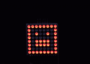
}Output:
The above code will display the following shape on our Dot Matrix.
Conclusion:
In this project simple we use a dot matrix to display different shape by using Arduino. Moreover we learn how dot matrix is connected with a circuit and how can we write code for different displays on dot matrix.
Also see other projects
- Arduino Project: How to control the speed of DC motor?
- Arduino Project: Send Command with Serial Communication
- Arduino Project: LED Fire Effect
- How to select an Arduino?
- How Raspberry Pi Is Better than Arduino For Learning Electronics?
- How to design an LED Flasher on Arduino Board
- Design an Arduino based gas leakage detector
- Design of Traffic Light Control system using Arduino
- How to Design RGB Mood Lamp using Arduino?