What is the Pulse Width Modulation?
What are the types of Pulse Width Modulation Technique (PWM)? Pulse Width Modulation(PWM) technique is used for controlling the AC output of power electronics converters. In this technique duty cycle can be varied from high frequency to some desired low frequency output current/voltages. Modulation techniques have always been of great interest for researchers from many years and still they attract many new researchers.
All the modulation techniques produce the train of switching pulses with some unwanted harmonics present in them that need to be minimized. There are many PWM schemes but each scheme needs to satisfy two objectives:
- How to calculate the converter switching ON time?
- How to reduce the harmonics present in the desired output?
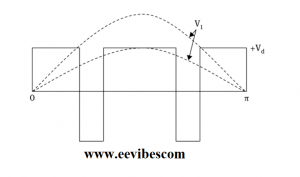
The dc input that is applied to the inverter is chopped by the switching circuits present in the inverter circuit. Duty cycle helps to control the harmonics and amplitude of the AC output voltages. For a square wave output the fundamental voltages (V1) has the magnitude 4Vd/π. The amplitude V1 is reduced because of the notches as shown in the figure below.
What are the types of Pulse Width Modulation Technique(PWM)?
Based on the methods of implementation, there are many PWM techniques. Each technique aims to produce the sinusoidal voltages of the desired fundamental frequency and amplitude. But for the inverter circuits because of the presence of harmonics, it is not possible to reduce the distortion. The magnitude of lower-order harmonic voltages can be reduced by controlling the switching. But this also results in increase of magnitude of higher-order harmonic voltages.
This situation is acceptable because the higher-order harmonics can be filtered using the filtering circuits and capacitors specially like motors who have the ability to surpass the high harmonic currents.
In order to check the quality of the PWM signal produced by the inverter, a detailed harmonic analysis of output waveform can be done.
Basic PWM Techniques
Following are the basic PWM techniques:
- Single Pulse Width Modulation
Multiple Pulse Width Modulation
- Sinusoidal Pulse Width Modulation
Advanced Pulse Width Modulation Techniques
- Trapezoidal Modulation
- Staircase Modulation
- Stepped Modulation
- Harmonic-Injected Modulation
- Delta Modulation
- Space Vector Pulse Width Modulation
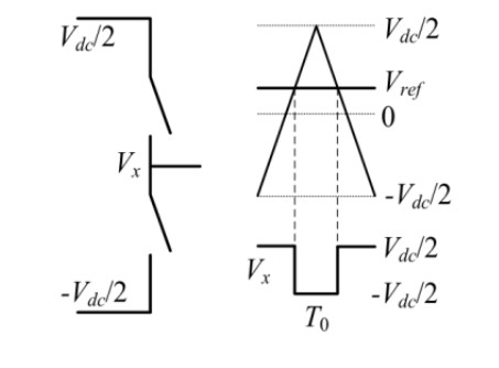
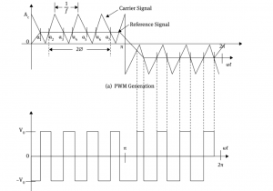
What is Single Pulse Width Modulation?
In this technique there is only one pulse present half per cycle. Here the width of the pulse is varied to control the output voltages of the inverter. There is a reference signal (Rectangular) and a carrier signal (triangular). They both are compared for creating the gating signal as shown in the figure below.
The fundamental frequency of the output voltage is determined from the frequency of reference signals.
Advantages of Single Pulse Width Modulation
Because of the symmetry of output voltages along the x-axis, the even harmonics are not present and if we make the pulse width equal to 2π/n, then nth order harmonics can also be eliminated.
Disadvantages of Single Pulse Width Modulation
- Great deal of harmonic content.
- Low output voltage magnitude.
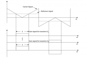
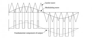
What is Multiple Pulse Width Modulation?
In this technique, many equidistant pulses are generated per half cycle. Harmonic contents are reduced because of the several pulses present per half cycle. The output of this technique is shown below.
Advantages
- Low Derating factor
- Reduced amplitude of lower-order harmonics
Disadvantages
- Less output voltages fundamental component
- Significantly increase in the amplitude of higher-order harmonics
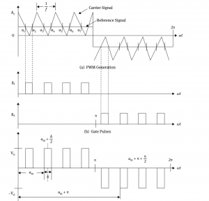
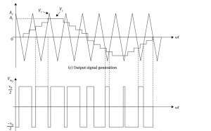
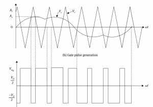
What is the Sinusoidal Pulse Width Modulation?
This technique is used at industrial level to control the output voltages of inverter. By comparing a reference signal with high frequency triangular signal, the ON and OFF instances can be determined of the pulse. As an output signal we get a modulation signal with a Sine wave. The frequency of modulation signal decides the frequency of output signal. Figure below shows this technique.
This is the most accurate modulation technique with minimum harmonics and it eliminates all the harmonics of order (2n-1).
Trapezoidal Modulation
Here the carrier (triangular) wave is compared with reference (Trapezoidal) wave the switching pulses are generated as shown below
This is called optimized PWM when the number of pulses is less than 15 per half cycle.
Stepped Modulation
This modulation technique produces low distortion but higher fundamental amplitude. Its input signal is stepped wave. The signal is divided into different intervals. Each interval is then controlled using different circuits. This is done for eliminating specific harmonics.
Harmonic Injected Modulation
In this modulation technique, the output signal is generated by injecting harmonics to the Sine wave. The higher amplitude of fundamental frequency and low distortion is produced as shown below
Also read form here
- What is the light emitting diode (LED)? How does it work?
- How Tunnel diode works?
- What are the switching circuits of diode? Examples and Problems
- How to test a diode? When diode is working and when it is not working?
- How zener diode is used for voltage and line regulation?
- What is the varactor diode and how does it work?
- what is the difference between drift and diffusion current of a diode?
- What is the barrier potential of PN junction diode ?