How to test a diode?
How to test a diode? Diode testing using digital multimeter is very common. When a diode is not connected in a circuit, we can test it using a multimeter. Multimeter testing is quite fast and reliable. If a diode is not faulty then it will show very low resistance with forward bias and a very high resistance like an open circuit with the reverse bias. If the diode is defectively open circuit, then it will show a very high resistance in both case: forward or reverse. A defective short circuit diode will show a very low resistance either forward or reverse biased. This type of diode is also called a resistive diode.
Testing through DMM
The digital Multimeter (DMM) has built in function for testing the diode. On the functionality button there is marked a diode sign which indicates where to test the diode. We need to set the knob here. Once it is set there, the internal circuitry of DMM has sufficient voltages for forwarding and reverse biasing the diode. Usually the range is from 2.5V to 3.5V. Different multimeters have different ways to show the results, some of them show the result in terms of voltages while mostly multimeters show the value of resistance as mentioned above. The following figure shows the multimeter testing of diode.
diode testing using digital multimeter when it is properly working?
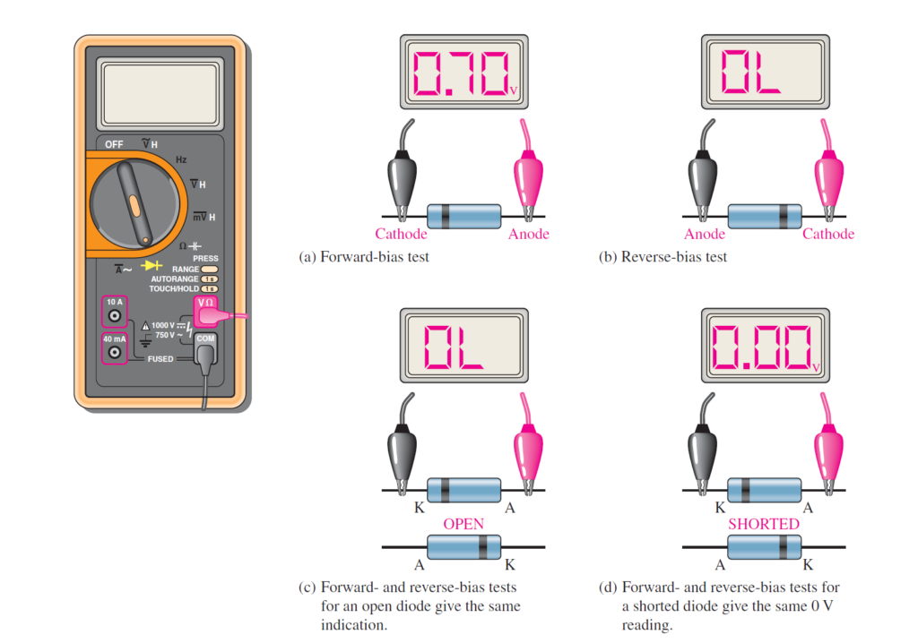
First of all set the knob of DMM at diode test button as indicated in the above figure. Connect the pink lead of DMM with the anode of the diode and the black lead with cathode of the diode. In this way diode is actually forward biased. You will see voltages between 0.5V to 0.9V. Generally the value is 0.7v as fig (a) shows. Now reverse the connections, and notice the DMM reading. If it shows “OL” (out of range) or very high value of voltages then it means the diode is properly working as indicated in fig (b)
diode testing using digital multimeter when it is properly working?
When diode is defectively open then it will show very large value of voltages for both connections i.e., forward and reverse. Usually the DMM will show ‘OL’ in this case as depicted in fig (c). When the diode is defectively short circuited, then it will show like zero resistance or 0v for both forward and reverse bias connections as shown in fig(d).
When DMM does not have diode test function then how to test the diode?
DMMs that don’t have a diode test position can be used to check a diode by setting the selection switch on an OHMs range. For a forward biased check of a normal diode, you will get an opposition perusing that can shift depending on the meter’s internal battery. Numerous meters don’t have adequate voltage on the OHMs setting to completely forward bias a diode and you may get a resistance value from a few hundred to a few thousand ohms. For the reverse bias check of a good diode, you will get an out-of-range sign, for example, “OL” on most DMMs in light of the fact that the reverse resistance is much high that can not be measured on DMM. Despite the fact that you may not get precise forward-and invert biased readings on a DMM, the overall readings show that a diode is working appropriately, and that is normally all you need to know. The out-of-range sign shows that the reverse resistance is very high, as you anticipate. The resistance value of a couple hundred to two or three thousand ohms for forward inclination is generally little contrasted with the reverse resistance, showing that the diode is working appropriately. The real resistance of a forward biased diode is generally less than 100 ohm .
Watch here:
https://www.youtube.com/watch?v=mMXDa5hVzXA
Also read here:
https://eevibes.com/solarpanel/
2 thoughts on “How to test a diode? When diode is working and when it is not working?”