Introduction to diode switching circuits
In this article we will be identifying forward and reverse biased operating modes of diodes present in the circuit. In large signal applications, the diodes are switched back and forth continuously. This switching means turning ON and OFF the diode rapidly. In such circuits, pulsating voltages are used. A high pulse means +5 volts and low pulse means 0 volts. So basically these high and low voltages cause the switching operation. Circuits that use such kind of switching operation are called switching circuits.
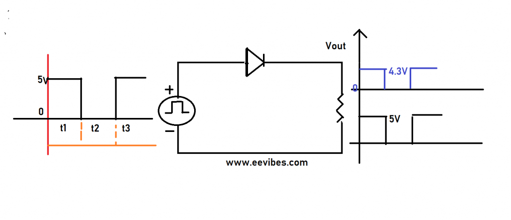
In the above circuit the digital signal having magnitude equal to 5V was applied and it was observed that for t1 the diode was ON. The output voltage waveform has the magnitude equal to (5V-0.7V=4.3V in case of Silicon diode). Output voltage is equal to 5V if we consider the ideal model of the diode.
In diode switching circuits, two or more diodes are used each of which is connected to independent voltage source. In order to understand the operation of switching circuits, we need to first determine which of the diodes is forward biased and which one is reverse biased. This is decided totally based on the basic concept of diode forward and reverse biased operations.
If anode is more positive with respect to cathode, then diode is forward biased otherwise it is reverse biased. Lets do some examples for understanding this concept.
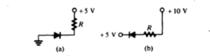
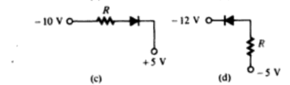
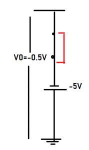
In figure (a) anode is connected to ground while cathode is connected to +5V. So anode to cathode potential is (0v-5v=-5V) negative. That’s why diode in figure (a) is reverse biased.
In figure (b) anode to cathode potential is [(+10)-(+5)]=+5V so that’s why diode in figure (b) is forward biased. Similarly for the figure (c) and (d) you can test diodes are (c) reverse biased and (d) forward biased respectively.
Diode switching circuit example 1
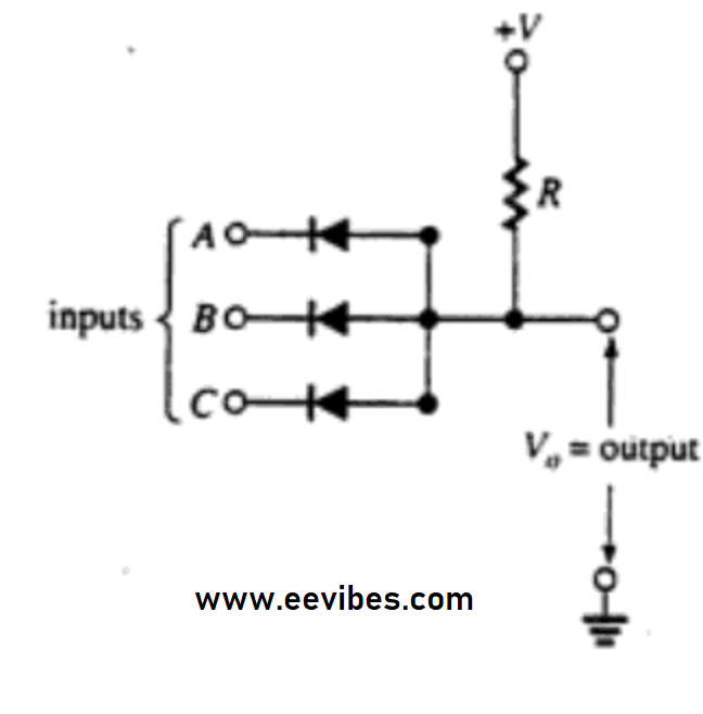
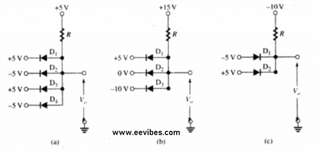
In the above circuit, all the anodes are connected to a common point from which the output is taken. While cathodes are connected to an independent voltage source. These are called the inputs of this circuit. All the voltages are measured with respect to ground.
Case 1: When all input voltages are same
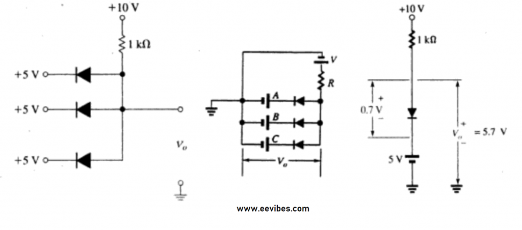
Now suppose that supply voltages at the anode terminal is (+10V) and inputs (A, B, C) are connected to +5V. All the diodes will be forward biased since anodes are more positive with respect to cathode. If we consider ideal model of the diode then voltage drop across it will be zero. So anode to cathode voltages =10-5=5. So output voltages are equal to 5v.
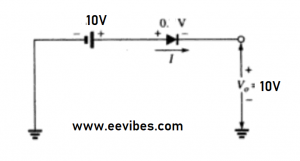
If we consider practical model of the diode then output voltages are equal to 5.7V. In order to get better idea of it, look at the following figure where two batteries are connected in series.
Case 2: When one of the inputs is 0 and others are non zero and equal
In this case lets assume that A=0v while B and C are equal to 5V while the source voltages are still same (+10V). Now this case is very interesting as output will be different as per your expectation.
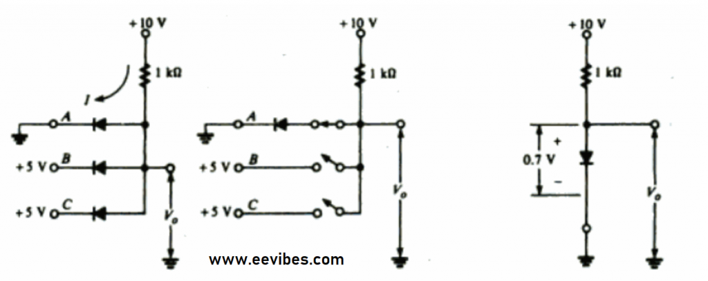
Here the scenario is little bit different. Since the current always follows the low resistive path that’s why the potential difference between source and input A is high as compared to the potential difference between source and other two inputs (B and C). So, the current will flow through the path shown below.
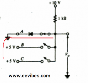
Because of the conduction through diode D1, the voltages at the output terminal will be around 0.7V in case of silicon and 0 in case of ideal diode.
Now the question is why not the other two diodes conduct? The answer is simple. Once the diode D1 goes into conduction it forces or bound the voltages at output terminal to be 0.7V which is actually the common anode of the other diodes. So the potential difference for diodes B and C is (0.7V-5v=-4.3V) negative which will force them to stay reverse biased.
3rd case: If all inputs are 0v
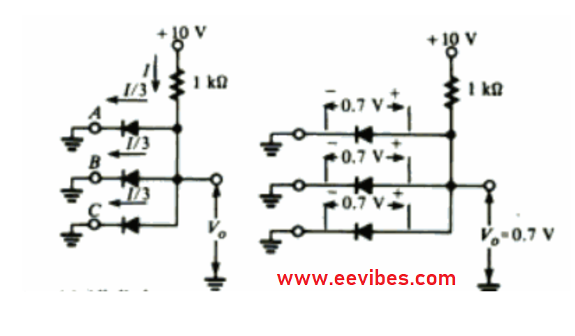
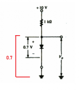
when all inputs are zero then all the diodes will have equal potential difference across their terminals. So all the diodes will be forward biased and the output voltages will be equal to 0.7V as shown in the above figure.
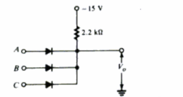
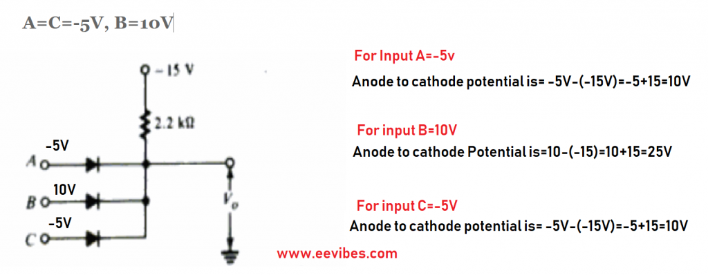
The inputs A, B, and C in the figure can be either 10V or -5V. Each diode is silicon. Find V0 for each of the following cases. (Assume ideal silicon diodes).
when A=B=C=-5V
A=C=-5V, B=10V
A=B=10V C=-5V
A=B=C=10V
Solution
In first case when A=B=C=-5V
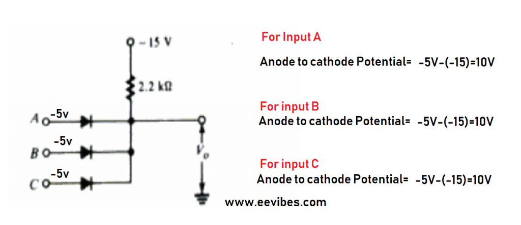
Since anode to cathode potential for all diodes is same so all diodes will be forward biased and the output voltages are determined as follows.
A=C=-5V, B=10V
A=B=10V C=-5V
in this case both diodes corresponding to input A and B will be forward biased while diode corresponding to input C will be reverse biased. Output voltages will be equal to 10V just like determined above.
A=B=C=10V
In this case all diodes will have equal potential difference across their terminals so they all will be forward biased. The output voltages will be 10V in case of ideal diode.
Diode switching circuits explanation with examples videos
Here is the complete explanation of diode switching circuits
Also read here
https://eevibes.com/electronics/what-is-the-diode-ideal-and-practical-model/