Design of Traffic Light Signals System on Arduino
ABSTRACT
Design of Traffic Light Control system using Arduino. In this project we will be using a set of lights and a push button. It will direct us for the crossing of road. Basically, we are designing a set of traffic Light system using Arduino board model R3 connecting breadboard with it and by programming the Arduino. The Arduino will be helping us to direct the cars when to be stopped by showing red light or turning on Red LED, and when the cars are set to go, by turning Green LED on. Arduino will tell us to do something when the we change the state of the buttons and that the Arduino is watching we can press the button to functions in code.
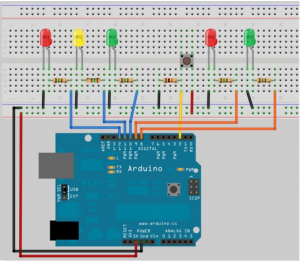
Circuit Diagram of Traffic signals control system using Arduino
Components of Traffic Signals Control System
The parts or the components that will be required for using this task will be given as follows.
- Arduino UNO
- 2 x red diffused LEDs
- 2 x green diffused LEDs
- 10k ohm resistor
- 5 x current limiting resistor 330ohms
- Push button
Arduino Board
Basically, what is an Arduino? It is a board on which a microcontroller is connected along with a crystal oscillator for providing a pulse to the microcontroller. Furthermore, it has some ports to plug in jumping wires for connecting it with your respective project on the breadboard. Beside this, the program is sketched by the computer application Arduino software. Furthermore, we connect the laptop with an Arduino board with a cable and, we provide DC power. In addition to this, it is an open-source electronics platform based on easy-to-use hardware and software. Arduino boards can read inputs such as we can say an input on a sensor, a finger on a button, or a message from an app like Twitter and turn it into an output activating a motor turning on a led publishing something online.
Working Procedure of Traffic signals Control System
Firstly, connect your circuit as shown in the figure. Double-check your wiring before providing any power to your Arduino. Remember to have your Arduino disconnected from the power while wiring the circuit. When you will be running the program, you will see that the car traffic light starts on the green, to allow cars to pass and the pedestrian on red. When we will be pressing the button then the program check that at least 5seconds have gone by since the last time. The lights were changed.to allow the traffic to get moving. And if they have passes the code execution to the function then we created a change lights ().in this function the car lights will go from green to then red and then the pedestrian light will go on green. After a period, which is being set in the variable cross-time which will allow enough time for pedestrians to cross the road in the given time the green pedestrian light will be blinking for the pedestrians to quickly pass the road after some time it will be changed to red and vehicle light will now go from the red to green and then the traffic can be resumed.
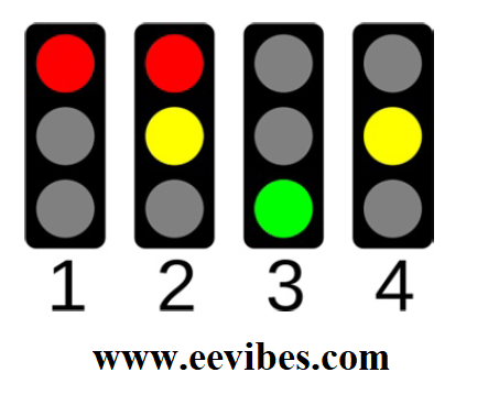
In Addition to this, we used 3 LEDS for controlling traffic i.e., Red for stopping, Green for allowing, and yellow for the delay between RED and Green. The time difference by which LEDs would glow respectively that is declared in the programming code.
We used resistors (5) for providing current to LEDs preventing them to fuse. We used a 10k ohms resistor for the push button. We used jumping wires to connect the breadboard project with Arduino and intra breadboard connections as well.
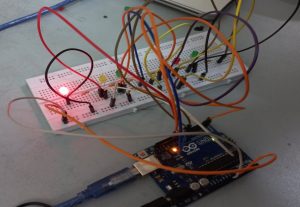
Simulation And Results
in this project, we used Arduino board model R3 to program a traffic control system on a breadboard using some LEDs (green, red, yellow), some resistors, and a push-button. We programmed the code in the Arduino computer application and using a data cable we uploaded the program to Arduino and hence got results.
Code for traffic light control system using Arduino
// Project 4 – Interactive Traffic Lights
int carRed = 12; // assign the car lights
int carYellow = 11;
int carGreen = 10;
int pedRed = 9; // assign the pedestrian lights
int pedGreen = 8;
int button = 2; // button pin
int crossTime = 10000; // time allowed to cross
unsigned long changeTime = 0; // time last pedestrian cycle completed
void setup () {
pinMode (carRed, OUTPUT);
pinMode (carYellow, OUTPUT);
pinMode (carGreen, OUTPUT);
pinMode (pedRed, OUTPUT);
pinMode (pedGreen, OUTPUT);
pinMode(button, INPUT); // button on pin 2
// turn on the green light
digital Write (carGreen, HIGH);
digital Write(pedRed, HIGH);
}
void loop() {
int state = digital Read(button);
/* check if button is pressed and it is over 5 seconds since last button press */
if (state == HIGH && (millis() – changeTime) > 10000) {
// Call the function to change the lights
changeLights();
}
}
void changeLights() {
digitalWrite(carGreen, LOW); // green off
digitalWrite(carYellow, HIGH); // yellow on
delay(1000); // wait 2 seconds
digitalWrite(carYellow, LOW); // yellow off
digitalWrite(carRed, HIGH); // red on
delay(2000); // wait 1 second till it’s safe
digitalWrite(pedRed, LOW); // ped red off
digitalWrite(pedGreen, HIGH); // ped green on
delay(crossTime); // wait for preset time period
// flash the ped green
for (int x=0; x<10; x++) {
digitalWrite(pedGreen, HIGH);
delay(1000);
digitalWrite(pedGreen, LOW);
delay(1000);
}
// turn ped red on
digitalWrite(pedRed, HIGH);
delay(1000);
digitalWrite(carYellow, HIGH); // yellow on
digitalWrite(carRed, LOW); // red off
delay(1000);
digitalWrite(carGreen, HIGH);
digitalWrite(carYellow, LOW); // yellow off
// record the time since last change of lights
changeTime = millis();
// then return to the main program loop
}
Design of Traffic Light Control system using Arduino
Also see
- Arduino Project: How to control the speed of DC motor?
- Arduino Project: Send Command with Serial Communication
- Arduino Project: LED Fire Effect
- How to select an Arduino?
- How Raspberry Pi Is Better than Arduino For Learning Electronics?
- How to design an LED Flasher on Arduino Board
- Design an Arduino based gas leakage detector