In this article we have described about Arduino Project: LED Fire Effect. As the name suggests, the purpose of this project is to give a stimulation of fire through LEDs by using Arduino. Now the question arises what makes this project much different from traffic lights project. In this project we will be using PWM also known as Pulse Width Modulation to give realistic effect of fire. In other words, by the time, fire will lit with different intensities throughout. Digital help will be used for getting analog results.
PULSE WIDTH MODULATION:
New keyword is used for this project that is PULSE WIDTH MODULATION also known as PWM. PWM is used to control the intensity of light. Light glows and fades as time passes. PWM can be found in File->Sketchbook->Examples->Analog menu of the Arduino software.
RESISTORS:
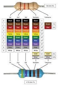
Resistors are used to reduce or act as a resistance to electric current. They also have other purposes such as :
- Adjust signal levels
- To divide voltages
- Bias active elements
- Terminate transmission lines
LED:
LED or light emitting diode. LEDs are used to emit light. Light is produced when current passes through a semi-conductor which then emits photons through the principle of electroluminescence.

ARDUINO BOARD:
Arduino boards are used as a brain of device as it has PIC microcontroller which itself has RAM, ROM and processor. It has different slots used for inputs/outputs and controlling voltage by giving Vcc and Vdd. It has crystal oscillator. Arduino board are mainly used for taking input from switches and sensors. It also controls physical outputs like lights, motors and actuators.

PROCEDURE:
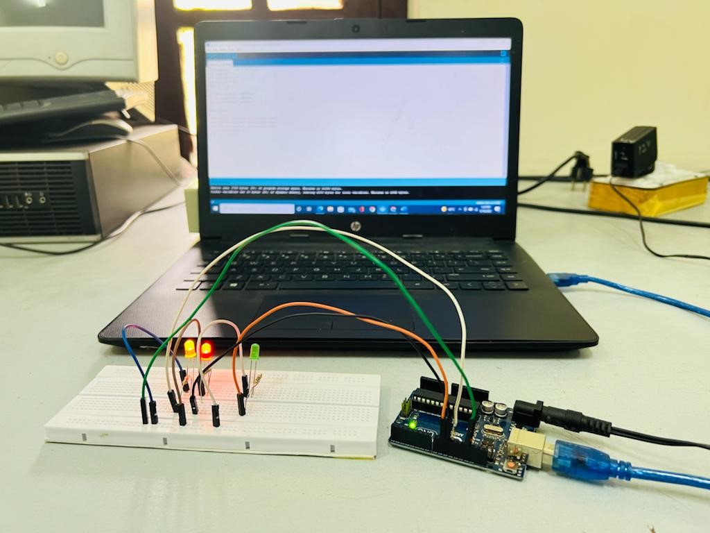
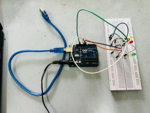
- Power up your Arduino board by plugging it in the socket.
- Used the USB cable to connect it with your Laptop.
- Insert Yellow LED first
- Put Red and Yellow LEDs in such a way that they have series connection with Yellow LED.
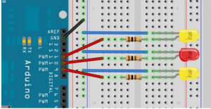
- Connect the resistors as shown in the diagram below.
- Use jumper wires to connect Arduino board with resistors.
- Use another jumper wire to ground the circuit.
SOFTWARE CODE:
Use the following code in your software:
//So let’s take a look at the code for this project. First we declare and initialize some integer variables that will hold the values for the digital pins we are going to connect our LEDs to.
int ledPin1 = 9;
int ledPin2 = 10;
int ledPin3 = 11;
//We then set them up to be outputs.
pinMode(ledPin1, OUTPUT);
pinMode(ledPin2, OUTPUT);
pinMode(ledPin3, OUTPUT);
//The main program loop then sends out a random value between 0 and 120, and then adds 135 to it to get full LED brightness, to the PWM pins 9, 10 and 11. analogWrite(ledPin1, random(120)+135); analogWrite(ledPin2, random(120)+135); analogWrite(ledPin3, random(120)+135);
//Finally, we have a random delay between zero and 100ms.
delay(random(100));
//The main loop then starts again, causing the flicker light effect you can see. Bounce the light off a white card or a mirror onto your wall and you will see a very realistic flame effect.
RESULTS:
Video of Arduino Project: LED Fire Effect
Also read here