Table of Contents
Introduction
Write a program forInterfacing of seven segment display with pic16F877A microcontroller using mikroC Pro. In this tutorial, I will guide you how to create a first project on mikroC Pro software for designing a counter using PIC16F877A microcontroller. First mikroC Pro code simulations will be shown. For checking the result PROTEUS simulations will also be shown. Finally I will show the results on PIC development board.
Basic components of the circuit involved
In this tutorial deign of 4 digit UP counter will be explained. The major components involved are mentioned below
- 4-digit seven segment display
- PIC16F877a Microcontroller
- Crystal Oscillator
- Bread Board
- Supply Voltages.
- PICKit 3 debugger
If you are using a PIC development board, then you can easily write and test your program.
Description of Components
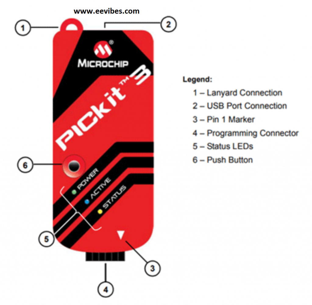
PICkit3 Programmer
In order to import the HEX file we need a programmer or burner that will actually transfer code to the ROM of microcontroller.
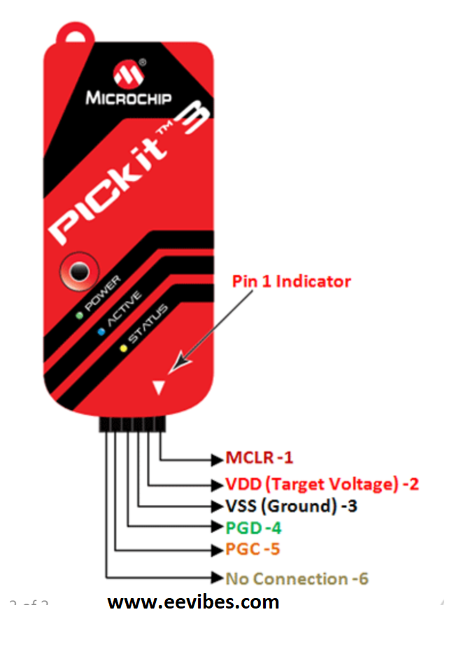
Here is the description of PinOut of PicKit 3
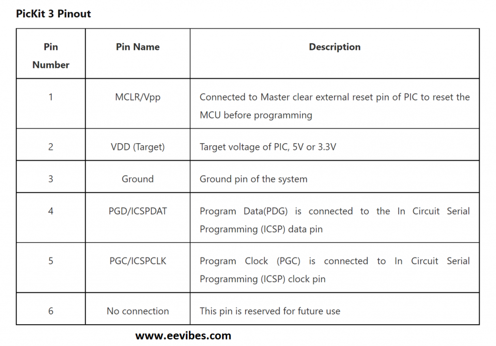
Pins connections of PICkit3 with PIC Microcontroller
There are three LEDs and a button on its front face. These LEDs have specific meaning and are named as
- Power LED: It lights up when PICkit 3 receives power.
- Active LED: If PICkit 3 establishes a connection with PC properly then it will light up the active LED.
- Status LED: It lights up yellow when PICkit3 is busy in writing program to the controller.
Seven Segment Display
Since the task is to design a 4 digit UP counter, that’s why there is a need of 4 digit seven segment display. Before learning how to use it let us first learn about the seven segment display.
What is the seven segment display?
A seven segment display is used for displaying the decimal numbers/digits form 0 to 9. There are 8 LED, 7 of which are used for displaying the digit/number while the eight one is used for displaying the dot in case of a decimal number.
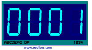
So with this arrangements of LED, any number ranging from 0 to 9 can be displayed.
There are two types of seven segments.
- Common Anode
- Common Cathode
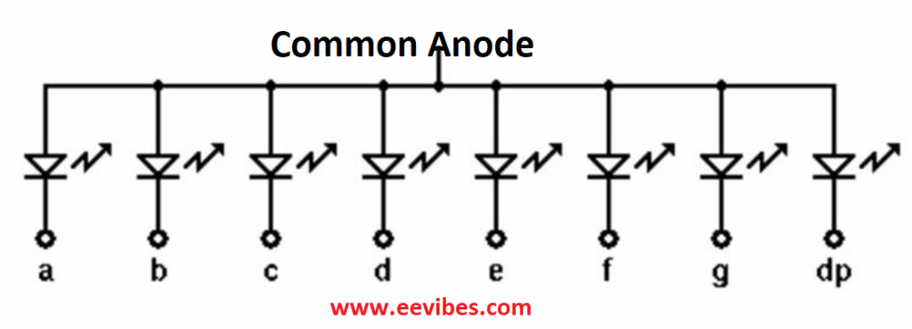
Common Anode Seven Segments displays
In these seven segments displays all the anodes of LEDs are tied together just like shown below and we need to apply separate signals at the cathode terminals for turning ON/OFF the particular LED. As we know that we can turn ON an LED if anode to cathode potential is High (+5V). Here anode is connected to +5V or Vcc and cathode is tied to 0v if we want to turn ON any particular LED.
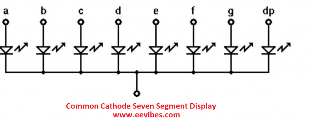
Common Cathode Seven Segments displays
In this type all the cathodes are tied together and hence we need to apply 0V or GND to this common terminal while any pin (a,b,c,d,e,f,g) will be connected to high logic level (+5V) in order to turn it ON.
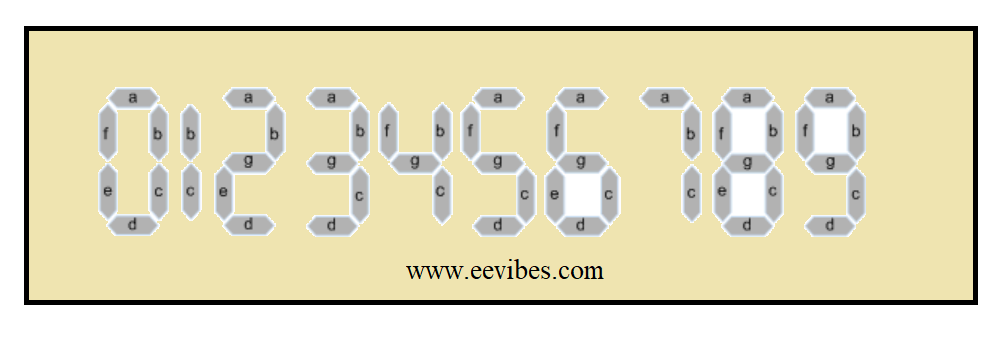
Lets see how these arrangements help to display a number
Code for 4 digit counter in C language
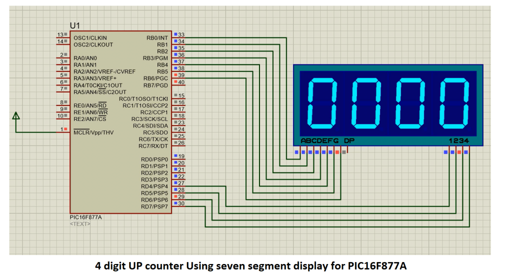
This code can be run either on MPLAB or MikroC Pro. For the time being I am using MikroC Pro as it is eay to configure. In this Project PORTB is used for connecting pins of seven segment display while PORTD last 4 pins (4,5,6,7) are used for selecting the segments. (S1,S2,S3,S4). As I have used common anode seven segment display thats why I have used the following sequence of Hex values for displaying the numbers. The Table Shows the exact values.
| Numbers | Hex values |
| 0 | 0xFC |
| 1 | 0x60, |
| 2 | 0xDA |
| 3 | 0xf2 |
| 4 | 0x66 |
| 5 | 0xb6 |
| 6 | 0xbe |
| 7 | 0xe0, |
| 8 | 0xfe |
| 9 | 0xf6 |
| #define segone 0x10 //for selecting D4
#define segtwo 0x20 //for selecting D5 #define segthree 0x40//for selecting D6 #define segfour 0x80 //for selecting D7
void delay_ms(unsigned int ms_count) { unsigned int i,j; for(i=0;i<ms_Count;i++) { for(j=0;j<1000;j++); } } int main() { char seg_code[]={0xFC,0x60,0xDA,0xf2,0x66,0xb6,0xbe,0xe0,0xfe,0xf6,0x77,0x7C,0x39,0x5E,0x79,0x71}; int cnt, num, temp,i; /* Configure the ports as output */ TRISB = 0x00; // Data lines TRISD = 0x00; // Control signal PORTD0-PORTD3 while (1) { for (cnt = 0x00; cnt <= 9999; cnt++) // loop to display 0-9999 { for (i = 0; i < 100; i++) { num = cnt; temp = num / 1000; num = num % 1000; PORTD = segfour; PORTB = seg_code[temp]; delay_ms(1);
temp = num / 100; num = num % 100; PORTD = segthree; PORTB = seg_code[temp]; delay_ms(1); temp = num / 10; PORTD = segtwo; PORTB = seg_code[temp]; delay_ms(1); temp = num % 10; PORTD = degone; PORTB = seg_code[temp]; delay_ms(1); } } } } |
Proteus Simulations for the seven segment UP counter
Also read here
- How to create a first project in PIC microcontroller using assembly language
- What are the conditional and unconditional branches in PIC microcontroller ?
- How to calculate the time delays in PIC Programming?
- How many types of PIC microcontroller are available in market?
- What is the minimum frequency signal that can be generated in PIC18F4550 microcontroller?